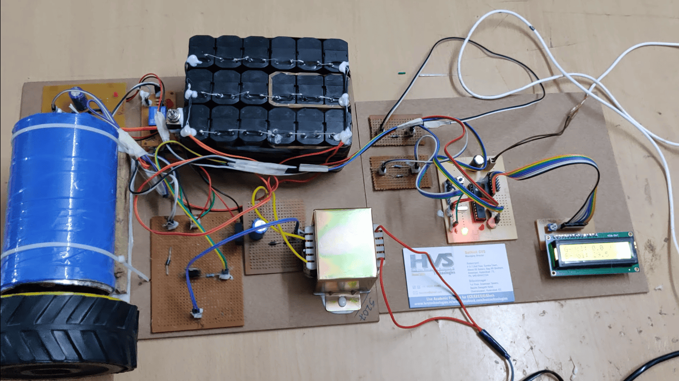
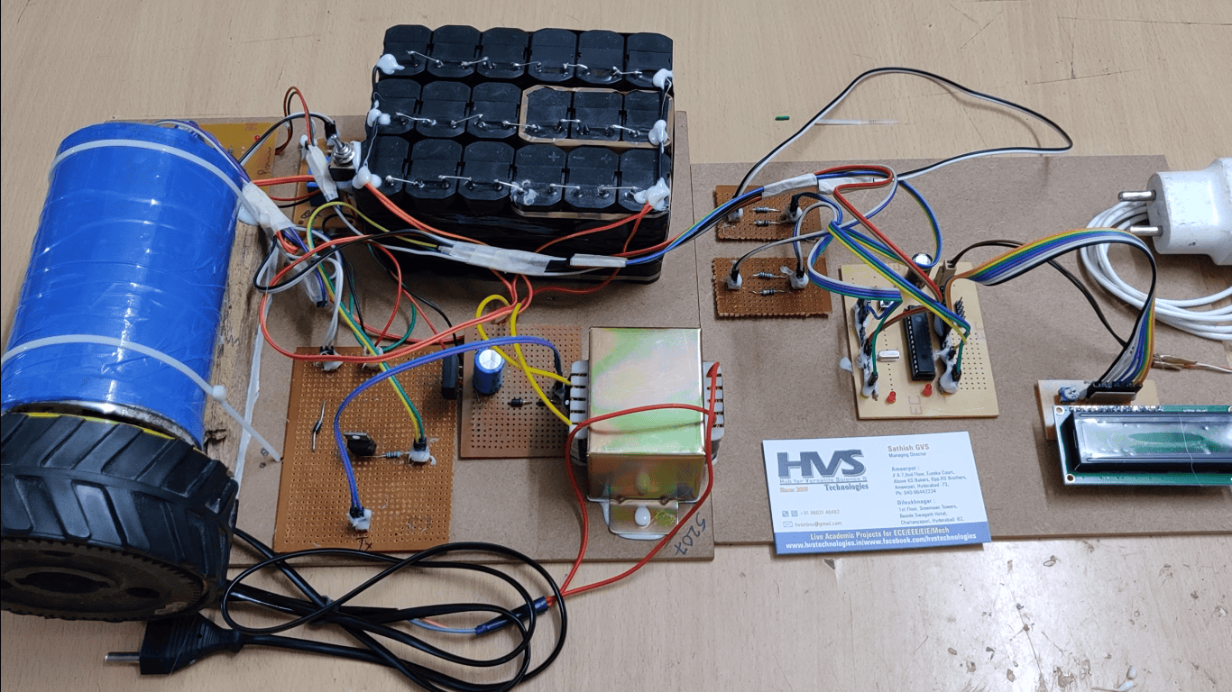
The Automatic Power Factor Correction (APFC) System is designed to improve the power factor of electrical loads automatically and efficiently. In many industrial and domestic electrical systems, inductive loads such as motors, transformers, fans, and fluorescent lamps cause the power factor to decrease, resulting in increased power losses, reduced efficiency, voltage drops, and unnecessary electricity charges. The objective of this project is to maintain the power factor close to unity by automatically switching capacitor banks according to the load conditions.
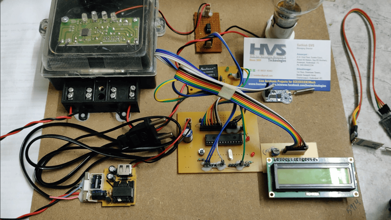
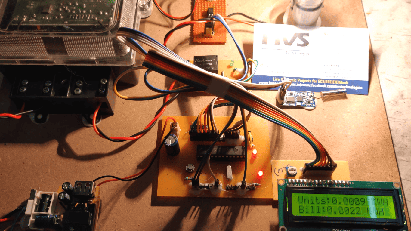
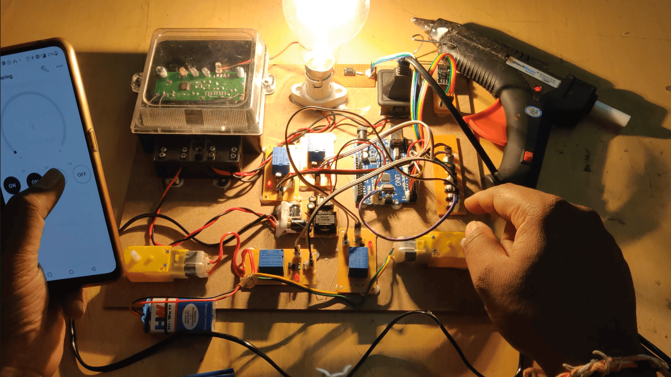
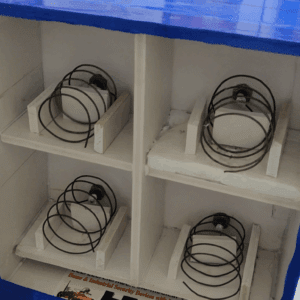
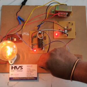
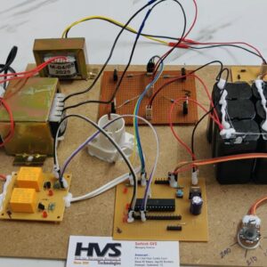
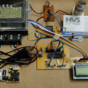
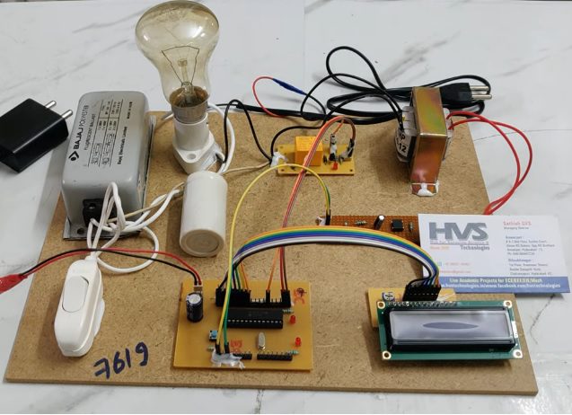
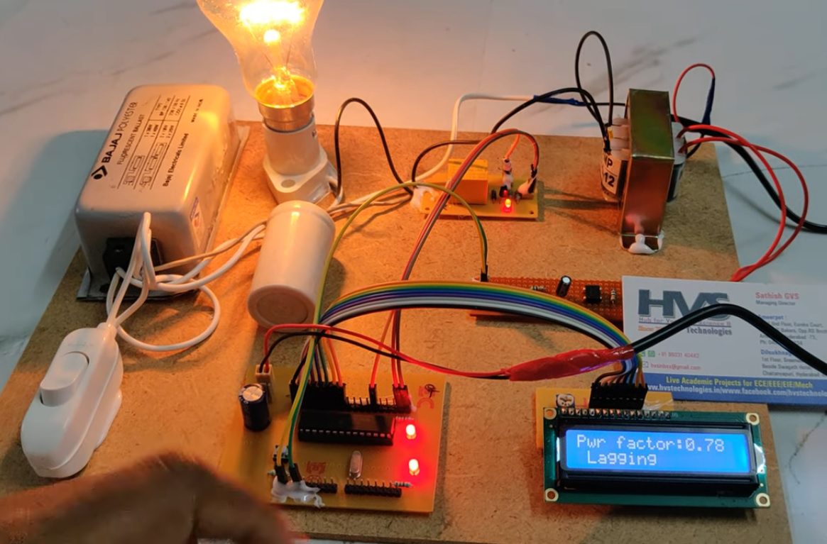
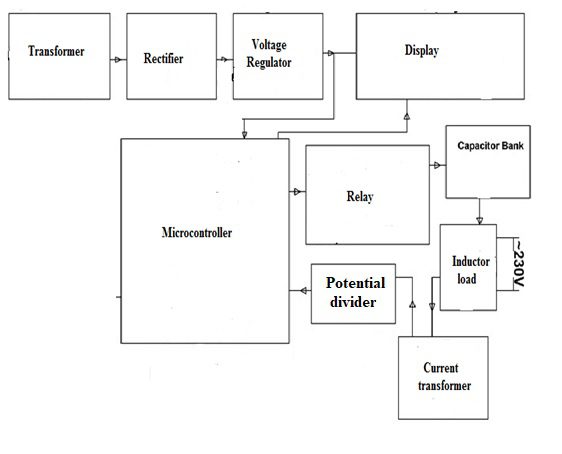
The proposed system uses a PIC microcontroller to continuously monitor the load condition and control the switching of capacitors through relay circuits. Depending on the reactive power requirement, the microcontroller connects or disconnects capacitor banks to compensate for the lagging power factor of the load. A 16×2 LCD display is used to display the system status and capacitor switching condition in real time. The system includes a regulated power supply, transformer, relay driver circuit, capacitor bank, and load section.
By automatically correcting the power factor, the APFC system reduces reactive power consumption, minimizes transmission and distribution losses, improves voltage regulation, enhances overall system efficiency, and helps avoid power factor penalties imposed by electricity utilities. The project provides a simple, reliable, and cost-effective solution for energy conservation and efficient power management in industrial, commercial, and institutional applications.
Objectives:
To design and implement an Automatic Power Factor Correction (APFC) system using a PIC microcontroller.
To continuously monitor the power factor of the connected electrical load.
To automatically switch capacitor banks ON and OFF through relay control based on load conditions.
To improve the power factor and maintain it close to unity (1.0).
To reduce reactive power consumption and minimize power losses in the electrical system.
To improve voltage regulation and overall energy efficiency.
To display the system status and capacitor switching condition on a 16×2 LCD display.
To provide a low-cost and reliable power factor correction solution for industrial and commercial applications.
 1 × ₹14,500.00
 video: