No products in the cart.


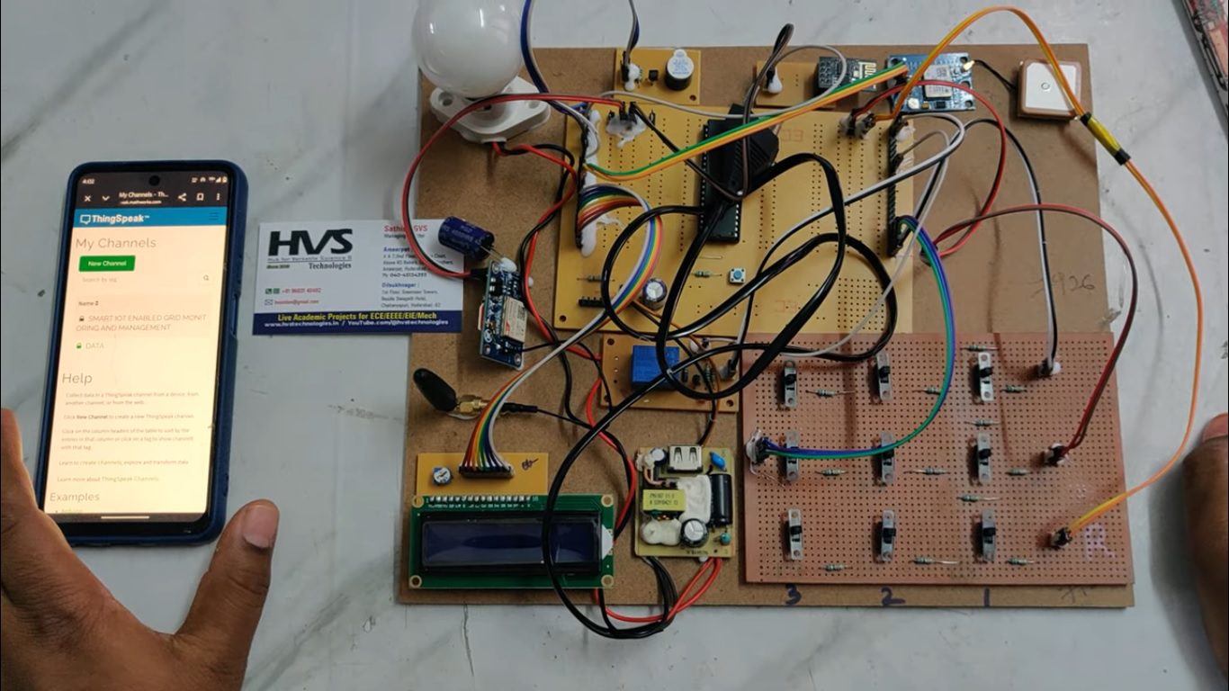
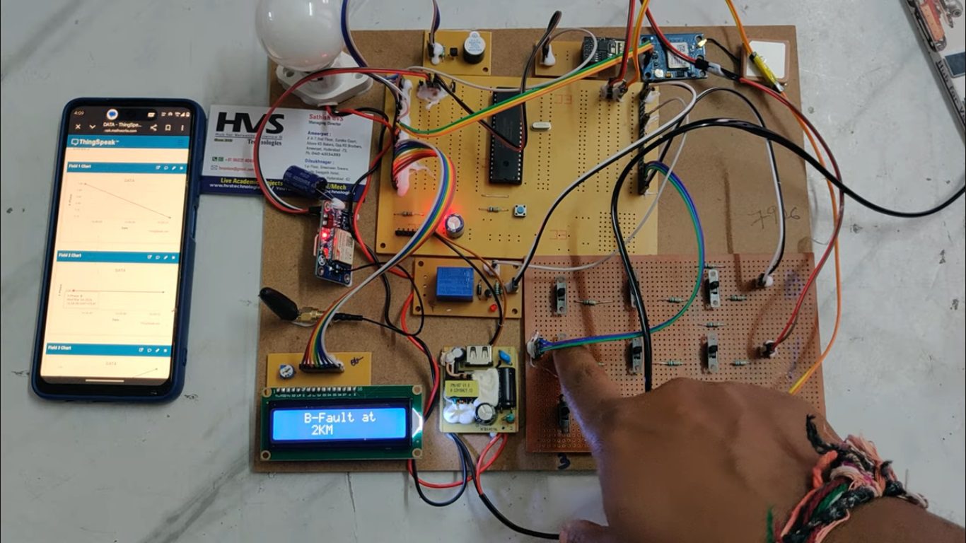
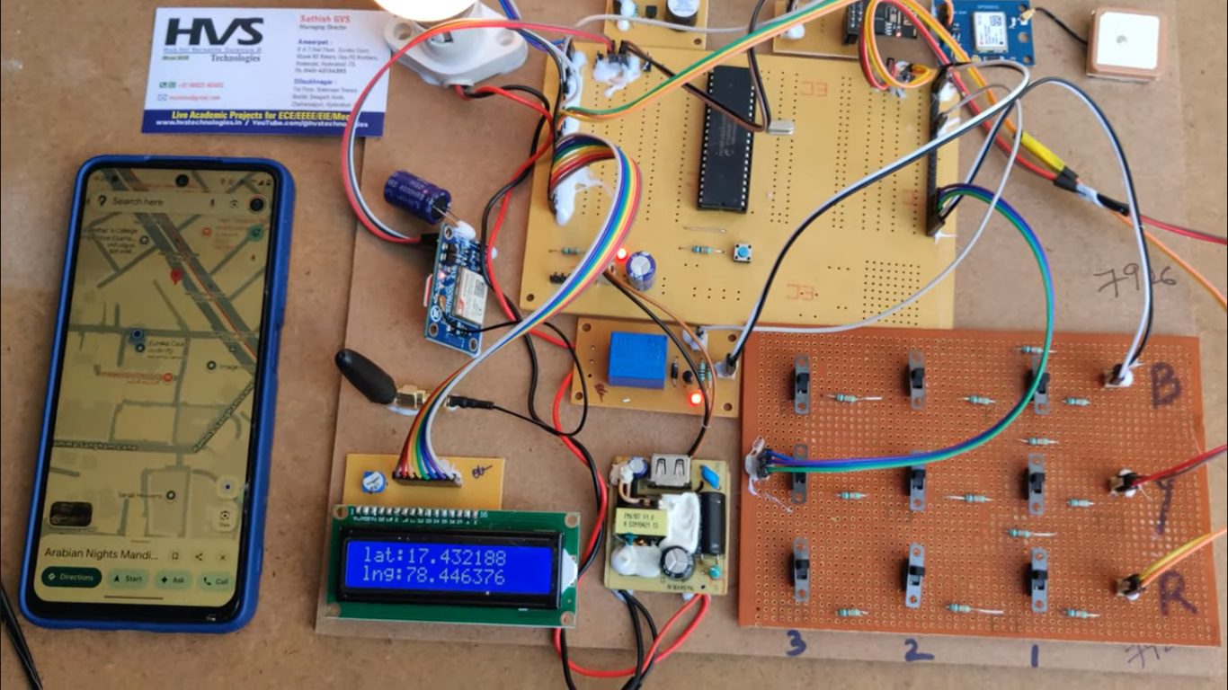
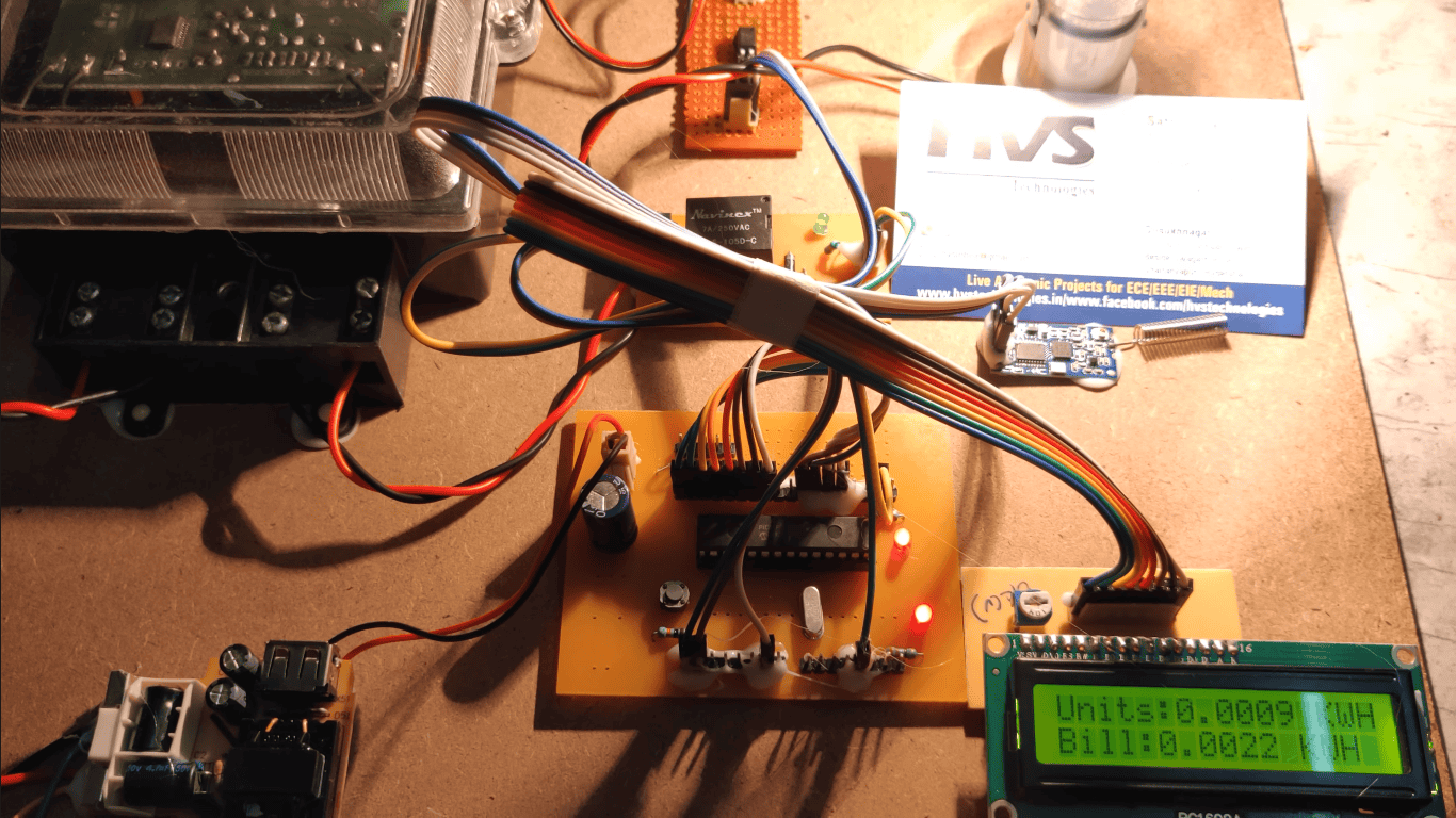
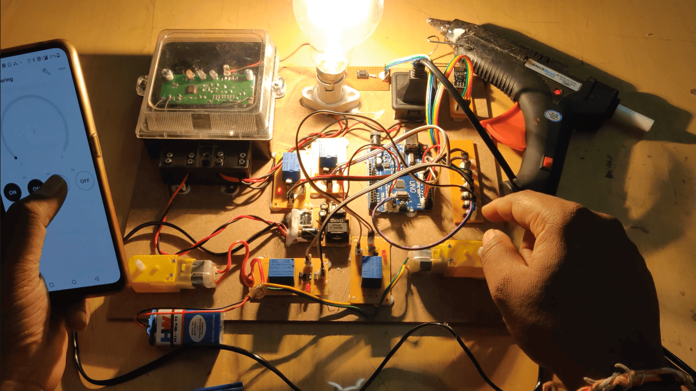
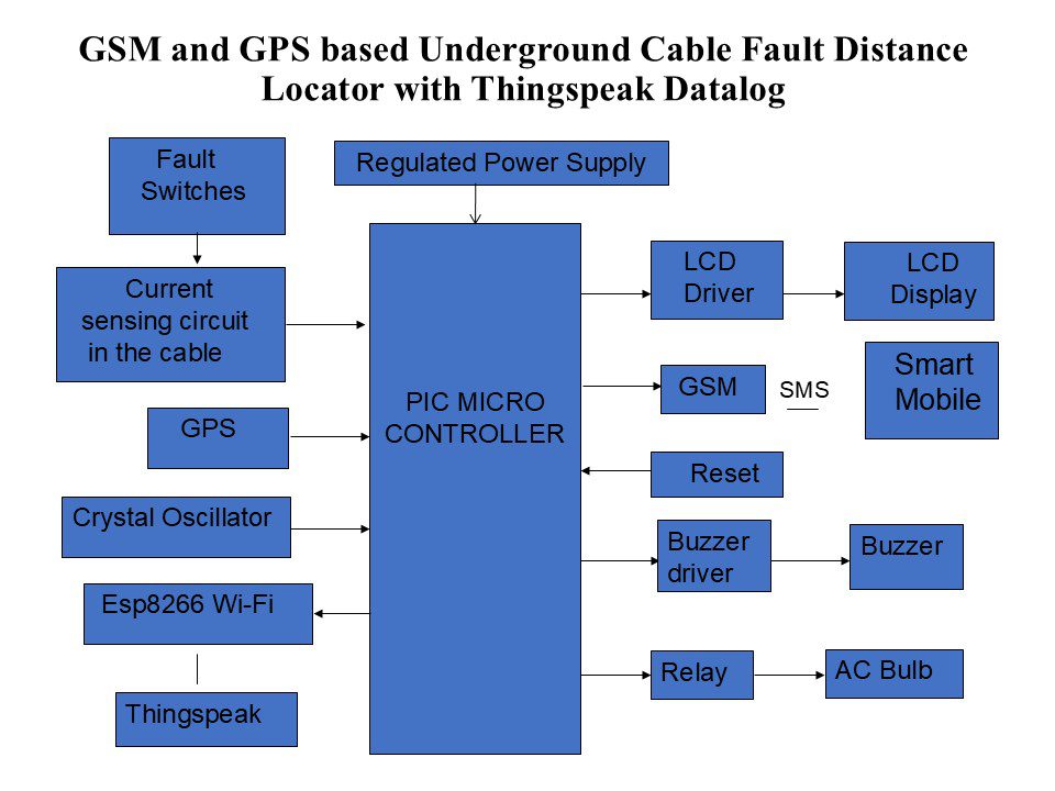
The IoT Based Underground Cable Fault Detection System is designed to identify the exact location of faults in underground cables and provide real-time monitoring. The system uses the principle of Ohm’s Law to calculate the distance of the fault from the base station by measuring voltage variations across cable resistors. A microcontroller processes the fault data and displays the fault distance and affected phase on an LCD.
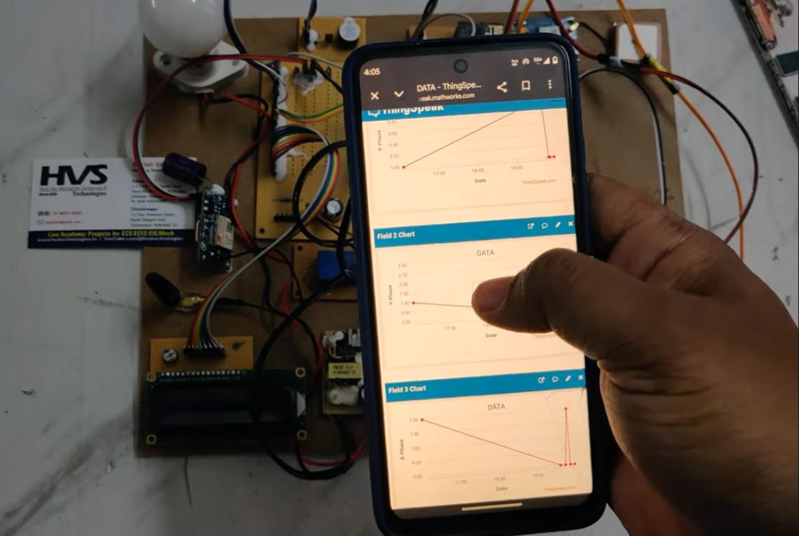
When a fault occurs, the system activates a buzzer and sends an alert message containing the fault location through GSM and GPS modules. The fault information, along with date and time, is uploaded to the ThingSpeak cloud using the ESP8266 Wi-Fi module for remote monitoring and analysis. A relay is used to isolate the faulty section, represented by a bulb in the prototype. This system helps in quick fault identification, reducing maintenance time and improving the reliability of underground power distribution networks.
Objectives:
 BLOCK DIAGRAM:
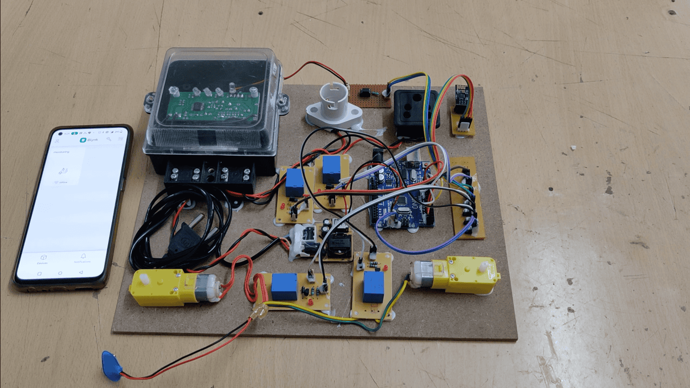
video:
BLOCK DIAGRAM:
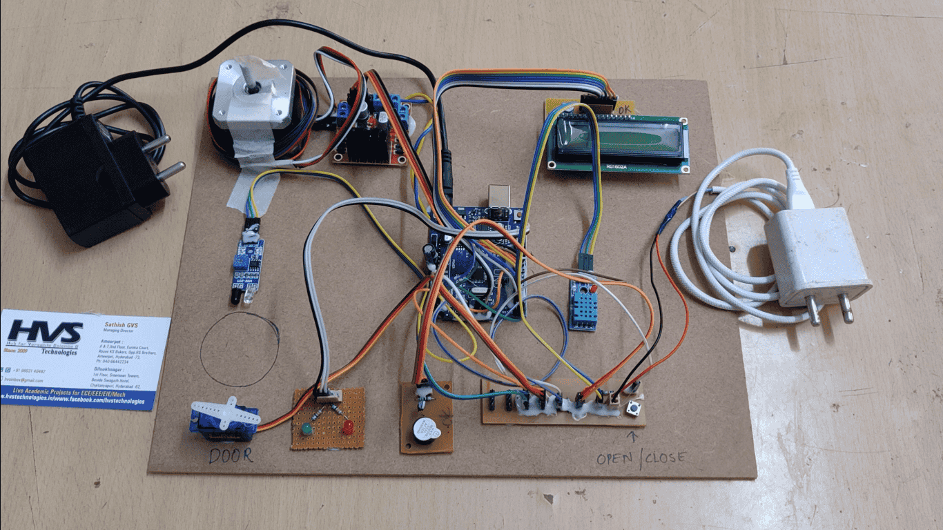
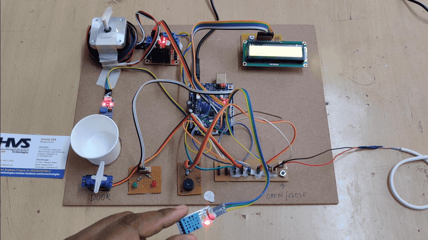
video:
- To detect underground cable faults accurately.
- To determine the fault distance from the base station in kilometers.
- To identify the faulty phase and display it on an LCD.
- To send fault alerts through GSM with location details.
- To obtain fault coordinates using GPS.
- To upload fault data to the ThingSpeak cloud using ESP8266.
- To provide real-time monitoring and data logging.
- To isolate the faulty section using a relay.
- To reduce fault detection and maintenance time.
- To improve the reliability of underground cable systems.
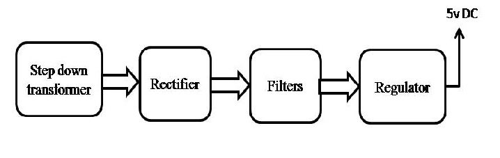
- Regulated power supply.
- PIC Microcontroller.
- LED indicators.
- Fault switches.
- GSM.
- GPS.
- Reset button.
- LCD with driver.
- ESP8266 WI-FI module.
- Buzzer.
- Crystal Oscillator.
- Relay.
- AC Bulb.
- PIC-C compiler for Embedded C programming.
- PIC kit 2 programmer for dumping code into Micro controller.
- Express SCH for Circuit design.
 BLOCK DIAGRAM:
 video: