No products in the cart.


This project presents a novel multi-output DC-DC converter based on Luo topology, designed for applications in electric vehicles (EVs) and renewable energy systems. The Luo converter topology is known for its high voltage gain, reduced voltage stress, and improved efficiency compared to conventional boost converters. By employing voltage lift techniques, the proposed converter effectively steps up the input voltage while providing multiple isolated or non-isolated outputs, making it ideal for applications requiring different power levels.
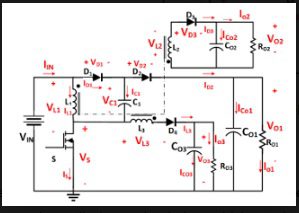
The LUO topology integrates inductors, diodes, and capacitors with a single-switch control mechanism, ensuring high efficiency and reduced circuit complexity. A detailed theoretical analysis is conducted to explore the converter’s operating principles, voltage gain characteristics, and mode transitions. Design considerations, including component selection and dynamic behavior, are discussed to optimize system performance.
Experimental results validate the proposed topology by demonstrating improved voltage conversion efficiency and stable multiple outputs. Additionally, a comparative study with conventional step-up converters highlights the advantages in terms of voltage gain, efficiency, and reduced electromagnetic interference (EMI).
The findings suggest that the proposed multi-output Luo converter is an excellent candidate for next-generation power management solutions in EV drivetrains, photovoltaic (PV) systems, and industrial applications, where multiple voltage outputs are required with high efficiency and reliability.
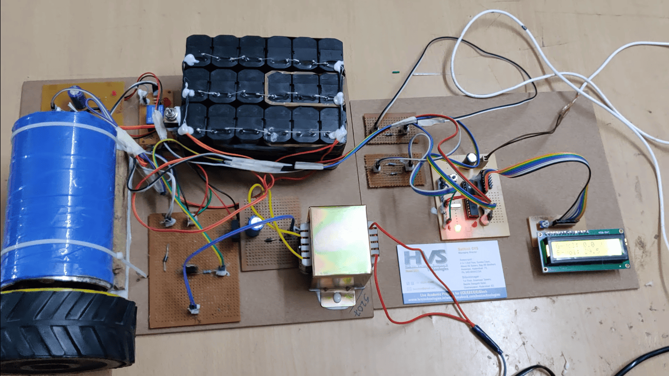
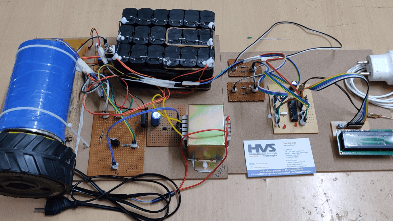
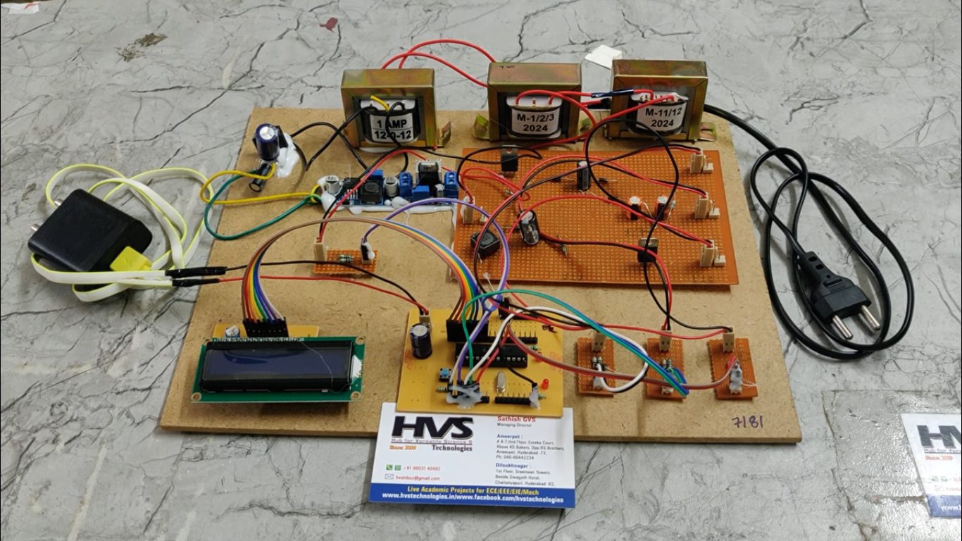
 The circuit shown in the image appears to be a multi-output DC-DC converter based on LUO topology. It consists of multiple inductors, capacitors, diodes, and switches, which are characteristic of boost, buck, or flyback converters used to generate multiple output voltages from a single input voltage source.
Working Principle:
Input Power Source (VIN):
The circuit shown in the image appears to be a multi-output DC-DC converter based on LUO topology. It consists of multiple inductors, capacitors, diodes, and switches, which are characteristic of boost, buck, or flyback converters used to generate multiple output voltages from a single input voltage source.
Working Principle:
Input Power Source (VIN):
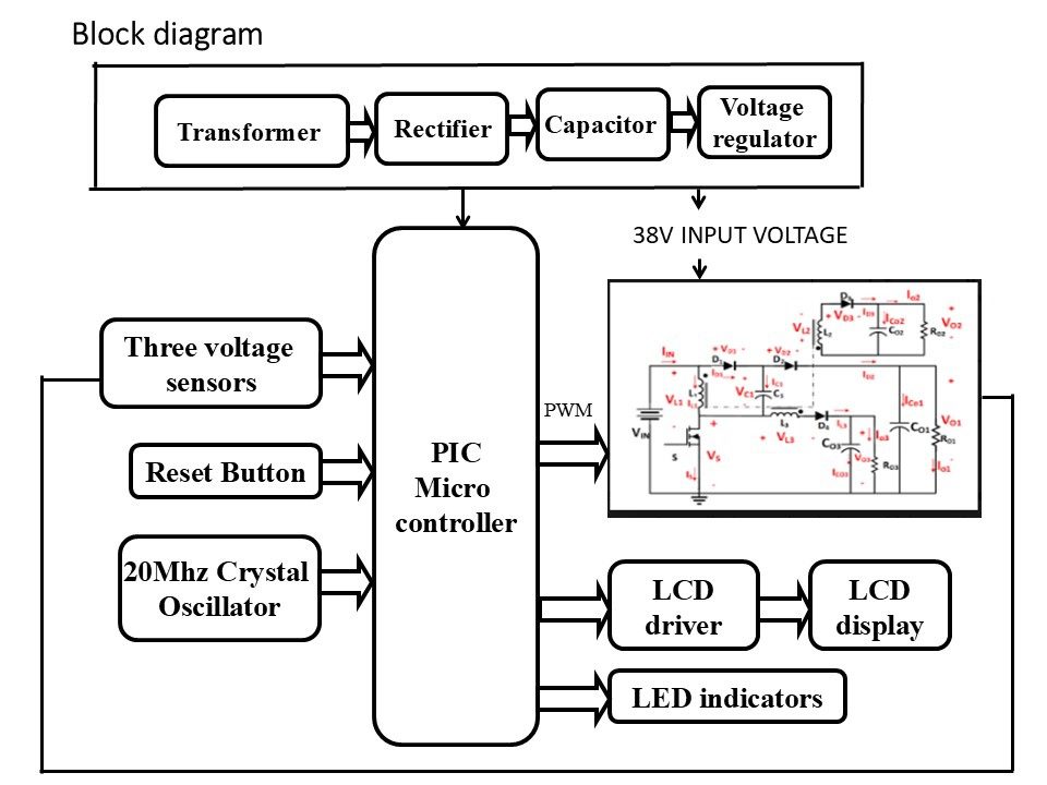
- The circuit takes an input voltage VIN(38V) from RPS( regulated power supply) and regulates multiple output voltages using switching techniques.
- A switch (S) is used to control the energy transfer.
- When the switch (S) is ON, current flows through inductors L1, L2, and L3, storing energy in the magnetic field.
- When the switch (S) is OFF, the inductors release stored energy, which is directed to the output stages via diodes.
- In this project we are using PIC16F72 Microcontroller to turn ON/OFF switch.
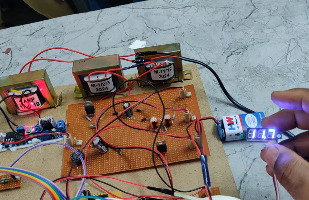
- The circuit has multiple outputs: VO1(12V), VO2(24V), and possibly VO3(36V).
- The diodes and capacitors in each output stage help in rectification and filtering to ensure a steady DC output.
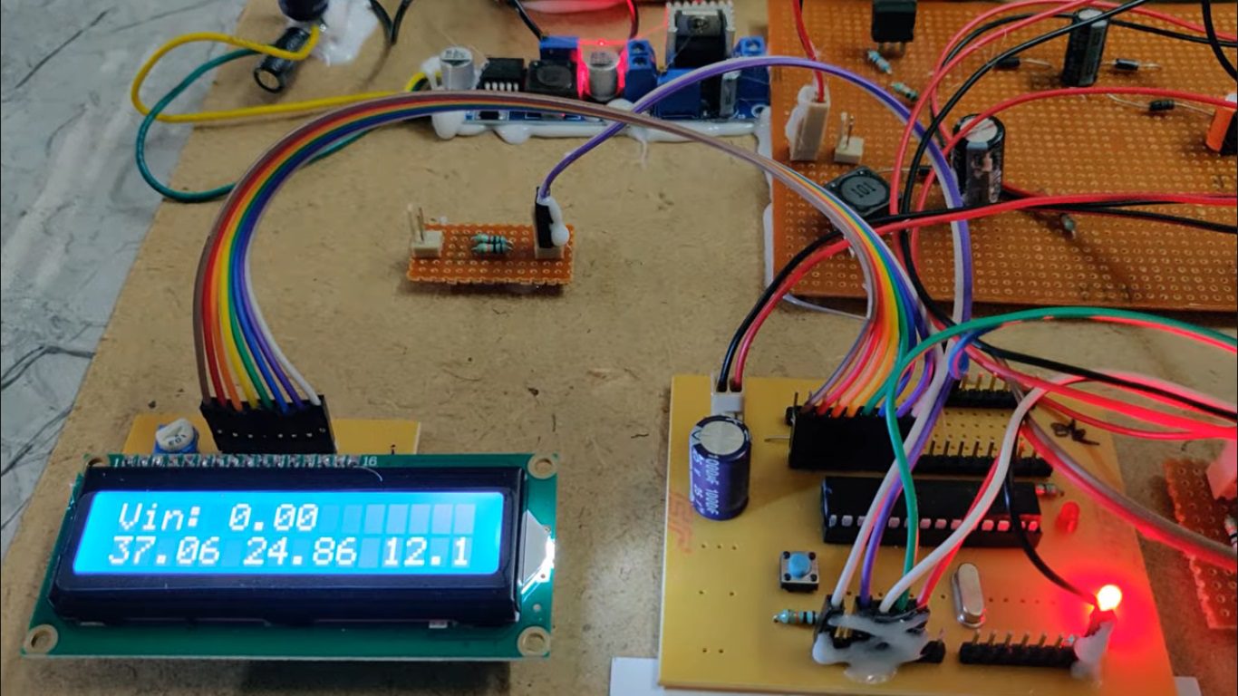
- Microcontroller will measure the multiple outputs from VO1, VO2 and VO3 will be display on LCD.
- Depending on how the circuit is configured, it can step up (boost) or step down (buck) the input voltage to the required levels.
- The inductors and diodes create isolated outputs with different voltage levels.
- Regulated power supply.
- PIC microcontroller.
- LCD display.
- Crystal oscillator.
- Three voltage sensors.
- Mosfet.
- Inductor.
- Capacitor.
- DIODE.