No products in the cart.


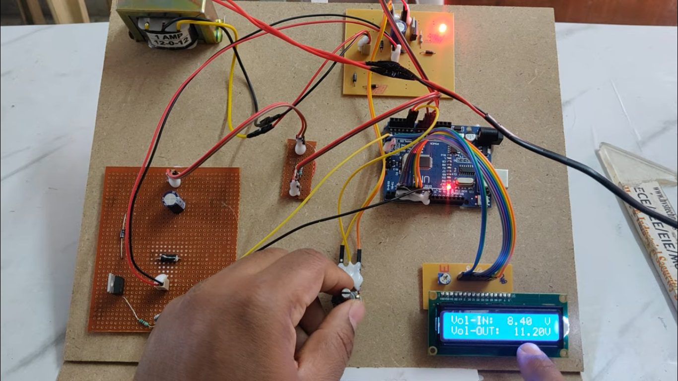

The project mainly aims in designing a Buck-Boost converter circuit using ARDUINO UNO microcontroller. The circuit is designed such that the voltage gets increased from 18v to 5volts using buck converter circuit and again from 5v to 12 v using DC-DC boost converter circuit.
This project deals with a new family of high boost voltage converters. The main objective is to obtain high step-up gain without operating at an extreme duty ratio. The voltage multiplier module is composed of a conventional boost converter and coupled inductors.
Among renewable energy systems, photovoltaic systems are expected to play an important role in future energy production. Such systems transform light energy into electrical energy, and convert low voltage into high voltage via a step-up converter, which can convert energy into electricity using a grid-by-grid inverter or store energy into a battery set. The high step-up converter performs importantly among the system because the system requires a sufficiently high step-up conversion.
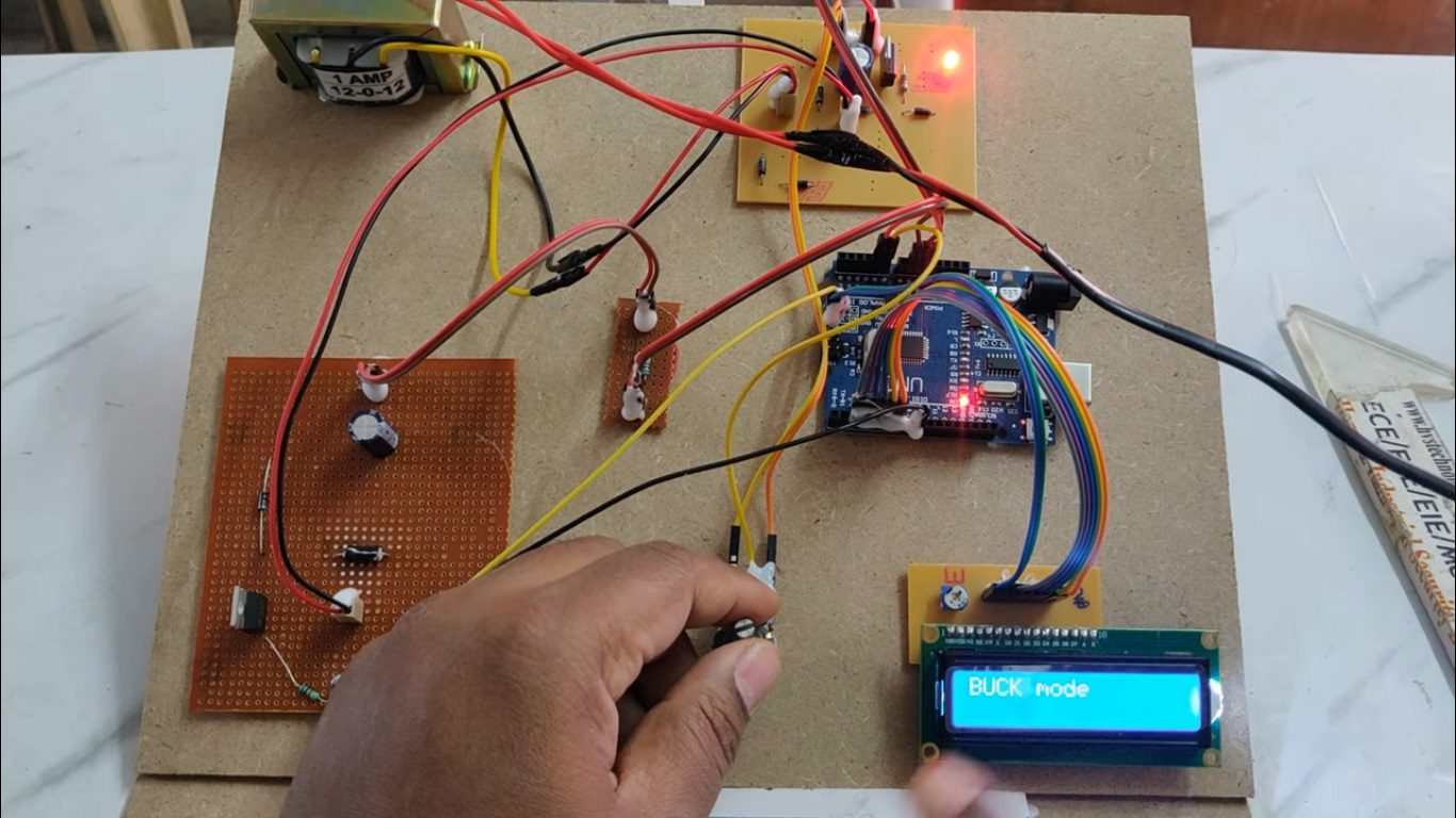
The voltage multiplier module (POT) is composed of a conventional boost converter and Buck converter. Firstly, we use DC-DC Buck converter circuit and an extra conventional boost converter is integrated into the second phase to achieve a considerably higher voltage conversion ratio. The two-phase configuration not only reduces the current stress through each power switch, but also constrains the input current ripple.
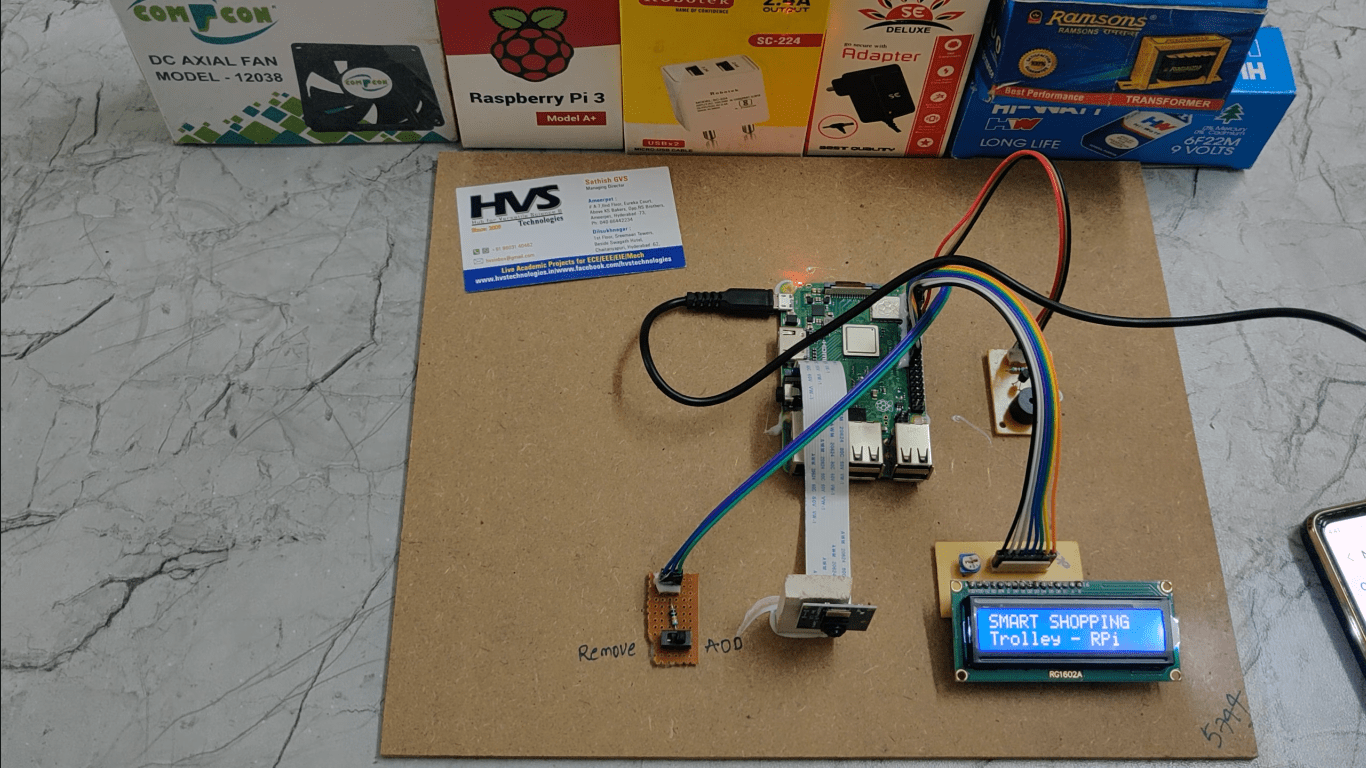
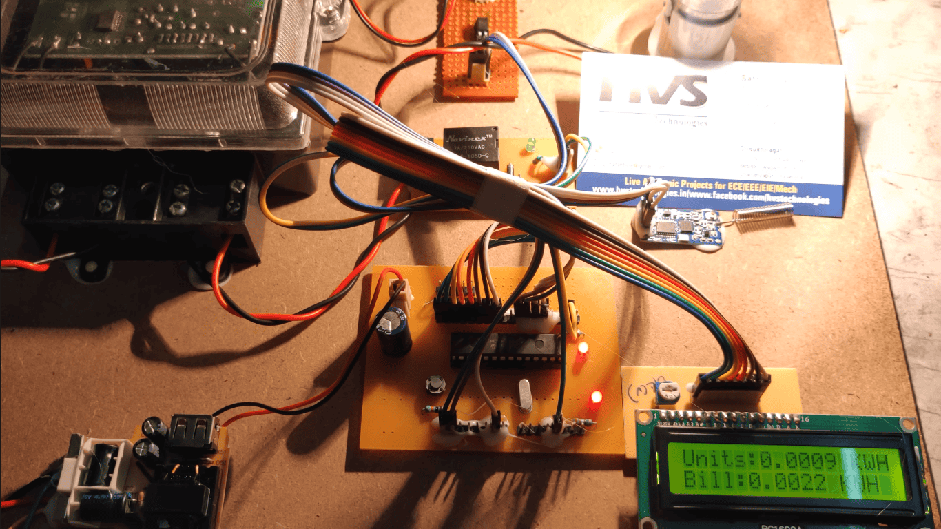
So, in this project, we make use of an onboard computer, which is commonly termed as micro controller. It acts as heart of the project. This onboard computer can efficiently communicate with the output and input modules which are being used. Here we use LCD module to the display the status of the voltage readings during the DC-DC conversion.
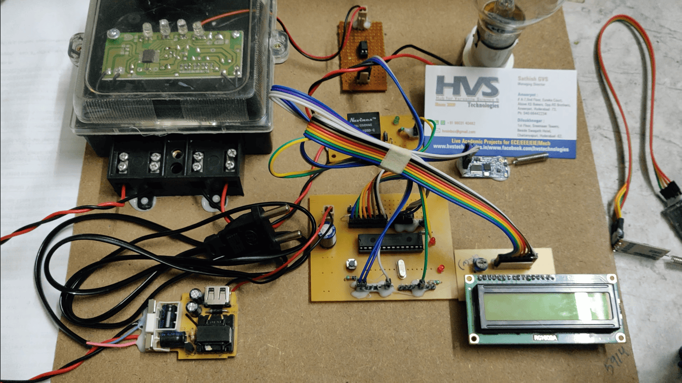
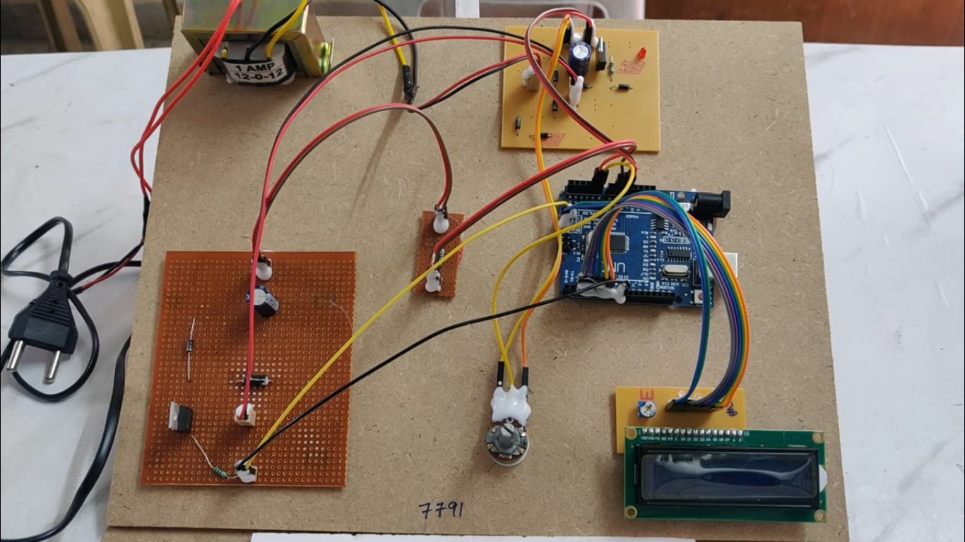
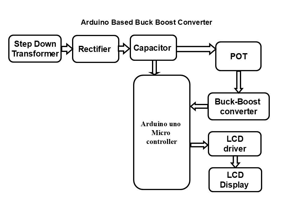
The major building blocks of this project are:
 video:
- Regulated power supply.
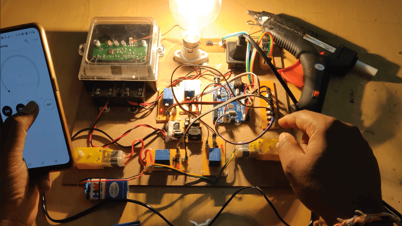
- Arduino UNO Micro controller.
- POT(potentiometer)
- Transformer.
- Capacitor.
- Diode.
- Rectifier.
- Buck-Boost Converter.
- LCD module.
- Embedded C programming.
- Arduino IDE programmer for dumping code into Micro controller.
- Express SCH for Circuit design.
 video: