
Subtotal ₹25,750.00


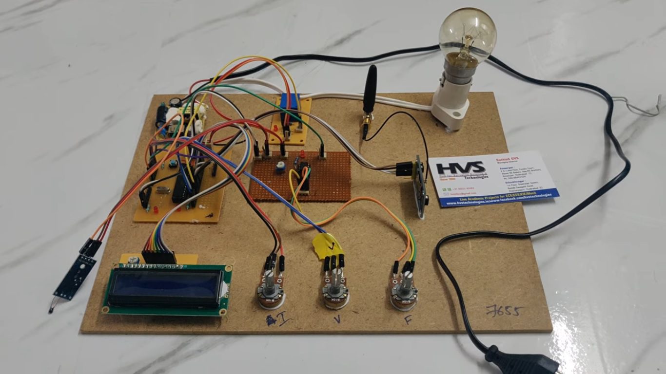
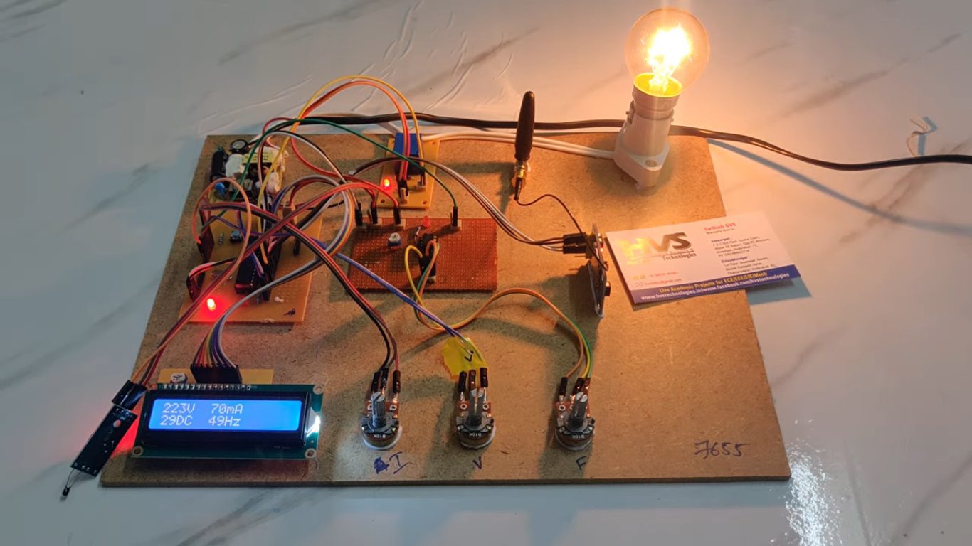
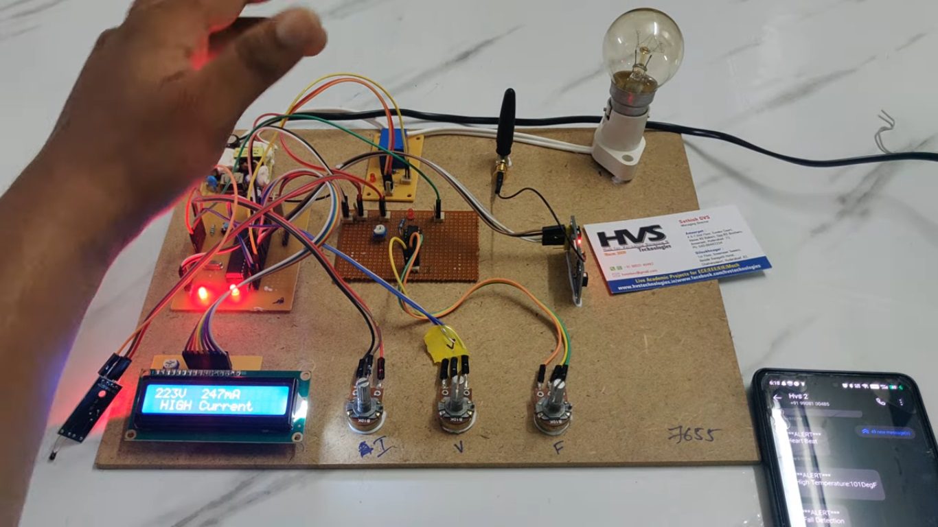
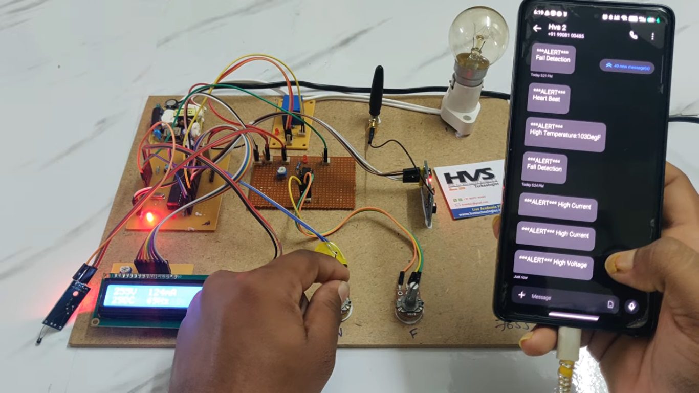

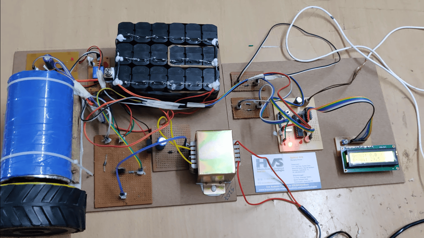
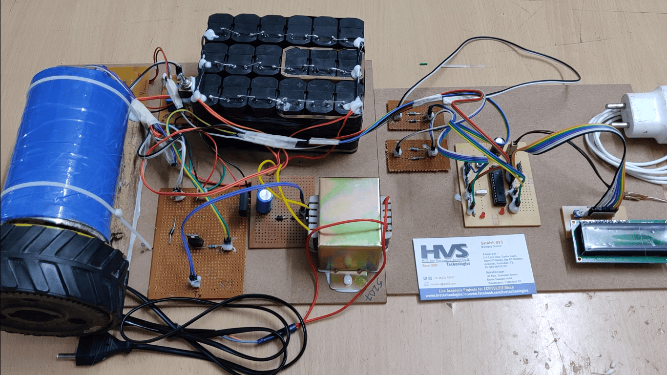
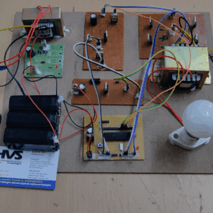
The project aims to develop a Power Grid Failure Detection System based on sensing frequency, voltage, current, and temperature parameters using a PIC microcontroller and GSM technology. The system continuously monitors the electrical parameters of the power grid through sensors and detects abnormal conditions such as voltage fluctuation, overcurrent, frequency variation, and overheating. Whenever any parameter exceeds the predefined safe limit, the PIC microcontroller identifies the fault condition and activates warning indications through LEDs and LCD display.
In addition, the GSM module is used to send instant alert messages to the authorized user or control station regarding the detected fault condition. A relay circuit is incorporated to control the connected load and protect the system during abnormal situations. This project provides reliable, real-time monitoring and quick fault identification, helping to improve power system safety, reduce equipment damage, and ensure uninterrupted operation of the electrical grid.
The main objectives of this project are:
 video:
To design a system for continuous monitoring of grid parameters such as voltage, current, frequency, and temperature.
To detect power grid failures and abnormal operating conditions automatically using a PIC microcontroller.
To provide real-time fault indication through LCD display and LED indicators.
To send instant alert messages to the user using GSM communication technology.
To protect electrical equipment by controlling the relay during fault conditions.
To improve the reliability, safety, and maintenance efficiency of the power distribution system.
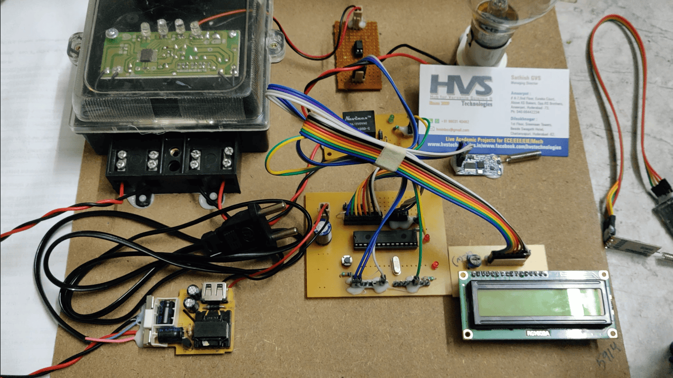
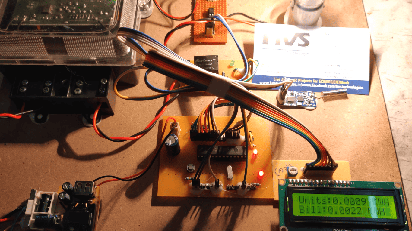
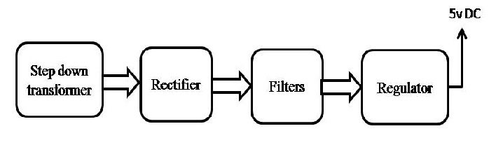
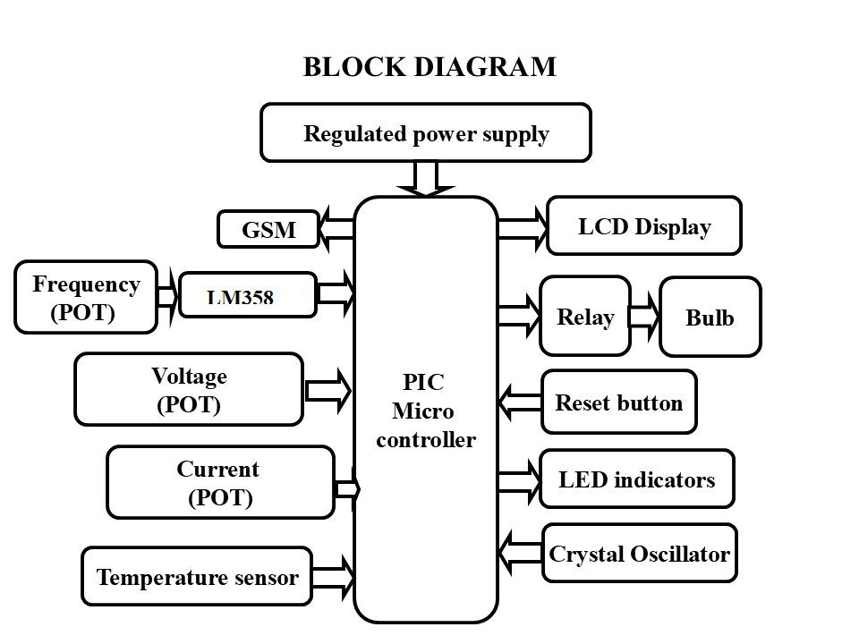
The major building blocks of this project are:- Regulated power supply.
- PIC Micro controller.
- LCD display.
- Buzzer
- LM358.
- Three POTs (Voltage, Current Frequency).
- GSM.
- Temperature sensor.
- Relay with AC Lamp.
- LED indicator
- Crystal oscillator.
- Reset Button.
- PIC Compiler for Programming.
- Express SCH for Circuit design.
 video: