No products in the cart.


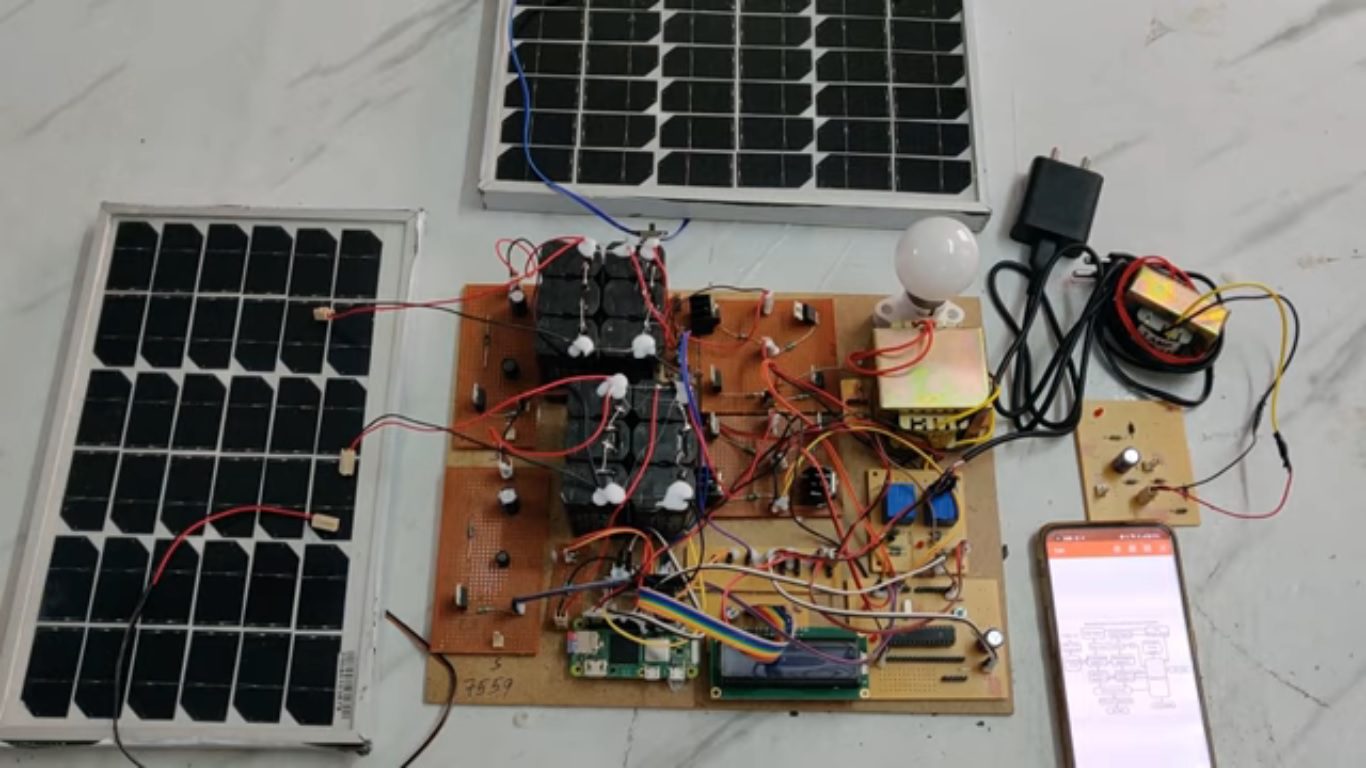
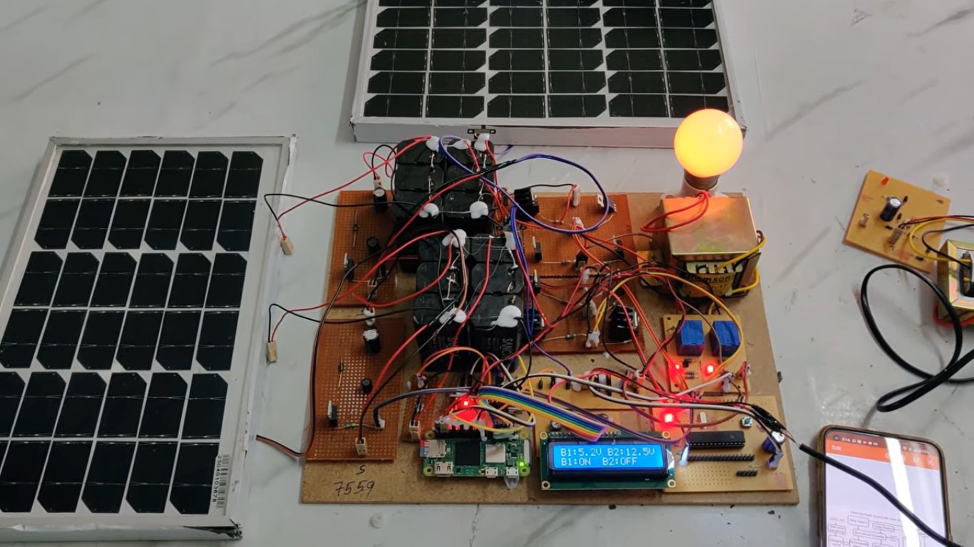
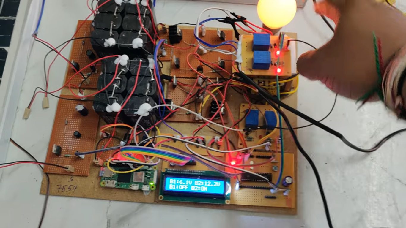
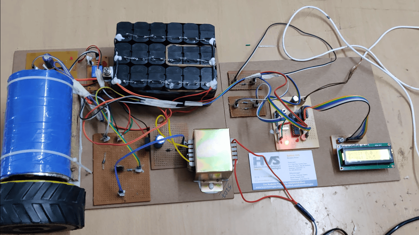
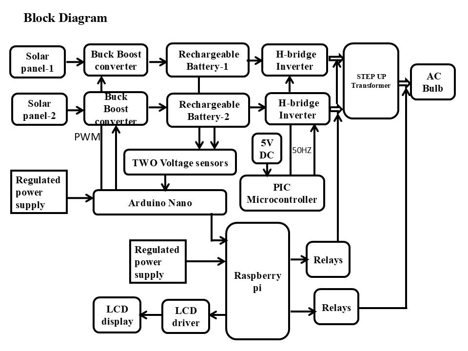
The growing demand for sustainable and reliable energy systems has led to the development of hybrid power solutions that integrate renewable energy sources with backup power systems. This project presents the construction of a solar-based micro-power grid with an automatic stand-by power source using a buck-boost converter and MPPT technique. The proposed system utilizes dual solar panels as the primary energy source, which charge rechargeable batteries through a buck-boost converter equipped with MPPT control to extract maximum power from the solar panels under varying environmental conditions. A Raspberry Pi is employed to monitor and control the system operation, including voltage regulation, MPPT implementation, source selection, and providing pulse-width modulation (PWM) signals to MOSFET inverters. In the event of insufficient solar energy, the system automatically switches to a stand-by power source through a charging circuit fed by a step-down transformer. The inverter and step-up transformer combination ensures AC output supply for loads such as bulbs. An LCD display, LED indicators, and reset options enhance system monitoring and user interaction. This design provides a low-cost, efficient, and sustainable micro-power grid solution with automatic backup functionality, making it suitable for rural electrification, emergency power supply, and standalone applications.
The main objectives of the project are:
 Block Diagram:
video:
Block Diagram:
video:
To design and implement a hybrid solar-based micro power grid that integrates renewable solar energy with an automatic standby power source for uninterrupted power supply.
To utilize a buck-boost converter with MPPT control to extract maximum power from solar panels under varying sunlight and temperature conditions.
To use Raspberry Pi as the central controller for system monitoring, source selection, voltage regulation, and generation of PWM signals for inverter operation.
To develop an automatic switching mechanism that activates the standby power source when solar energy becomes insufficient.
To implement an inverter and step-up transformer circuit for providing stable AC output to drive electrical loads.
To display system parameters such as voltage, current, and operational status on an LCD for real-time user monitoring.
The major building blocks of this project are:- Two Solar panels.
- Two buck-boost converters.
- Two Batteries.
- TWO H-Bridge circuits.
- Voltage sensors.
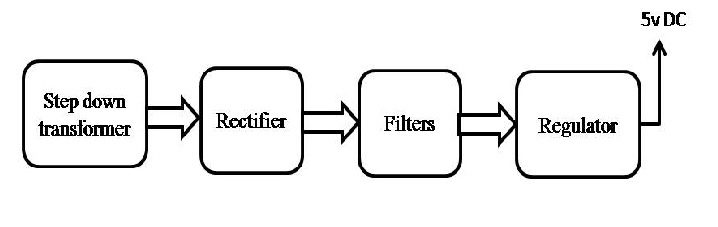
- Regulated power supply.
- Raspberry pi.
- Arduino Nano.
- PIC Microcontroller.
- LCD display with driver.
- Relays.
- Step UP Transformer.
- AC Bulb.
- Raspbian OS.
- Express SCH for Circuit design.
 Block Diagram:
 video: