No products in the cart.


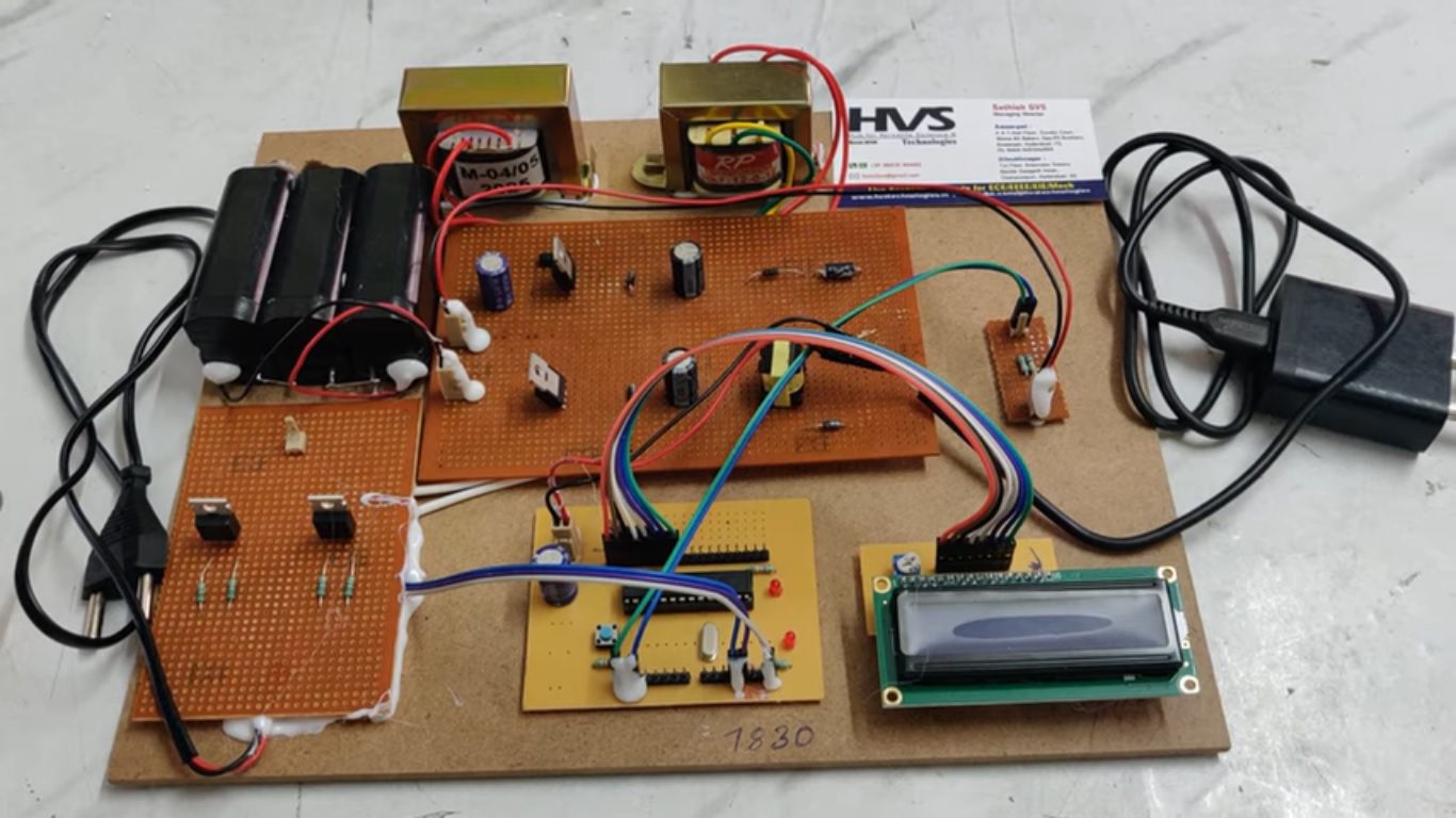
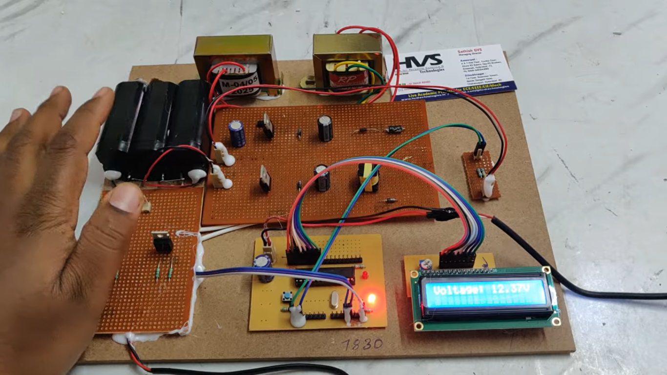
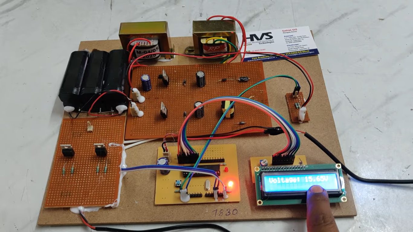
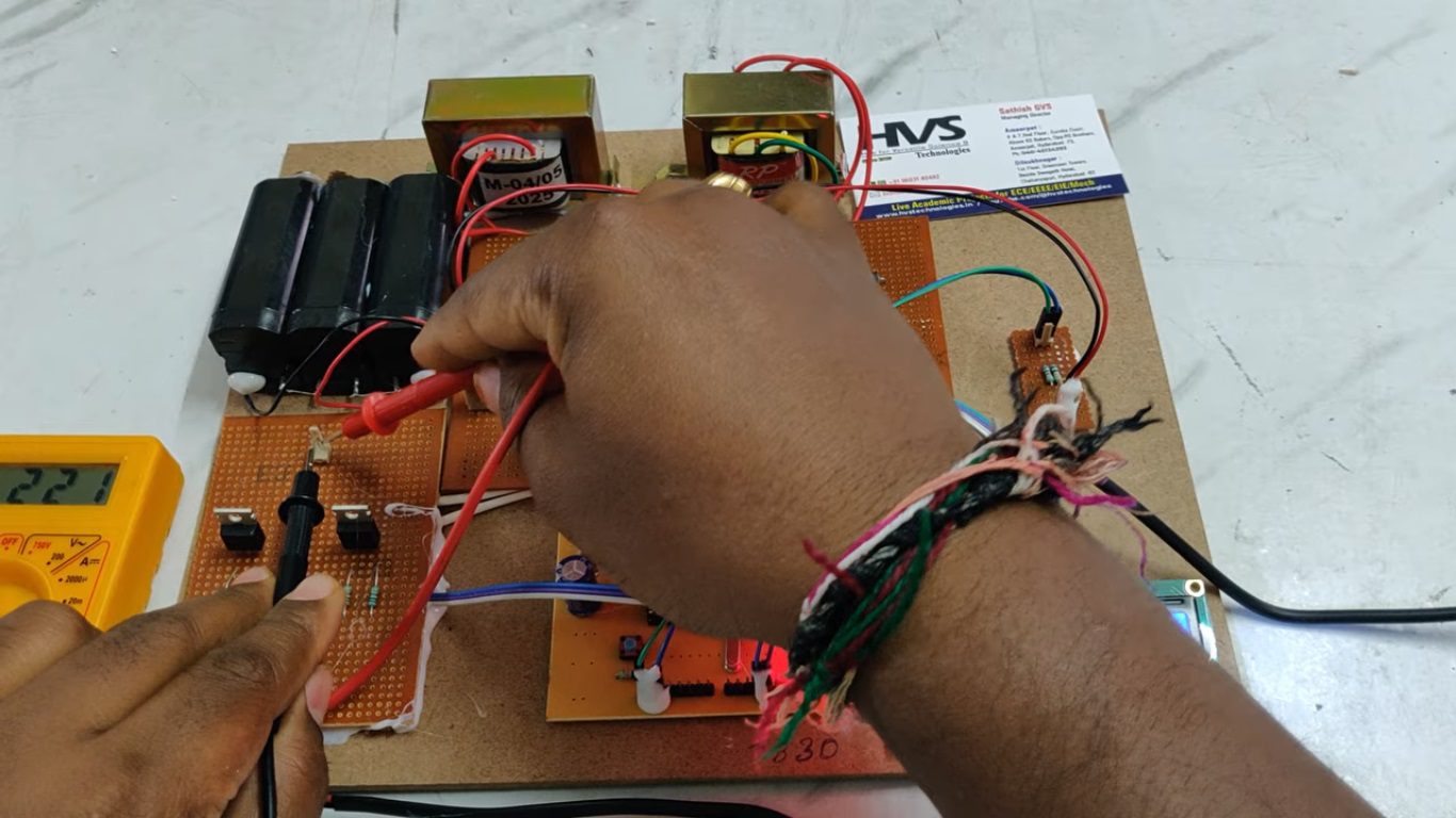
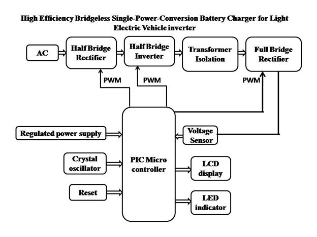
This project presents a high-efficiency bridgeless single-power-conversion battery charger designed for light electric vehicle applications. The proposed system begins with a half-bridge rectifier that converts the AC input into DC while reducing conduction losses compared to conventional bridge rectifiers. The rectified DC is then processed by a half-bridge inverter, which converts it into high-frequency AC using PWM signals generated by a PIC microcontroller. A high-frequency transformer provides electrical isolation and appropriate voltage conversion to ensure safe operation. On the secondary side, a full-bridge rectifier converts the high-frequency AC back into regulated DC suitable for battery charging. Voltage feedback from the output is sensed and fed to the microcontroller for precise control of the charging process. An LCD display and LED indicators provide real-time system status and charging information. The proposed charger offers improved efficiency, reduced power losses, compact design, and reliable performance, making it suitable for light electric vehicle battery charging systems.
Objectives of this project:- To design a high-efficiency bridgeless battery charger for light electric vehicle applications.
- To reduce conduction losses by using a half-bridge rectifier instead of a conventional diode bridge.
- To convert AC input power into high-frequency AC using a half-bridge inverter for efficient power processing.
- To provide electrical isolation and voltage conversion using a high-frequency transformer.
- To obtain regulated DC output using a full-bridge rectifier for safe battery charging.
- To implement PWM control using a PIC microcontroller for precise regulation of the charging process.
- To monitor output voltage through a voltage sensor to ensure reliable and safe operation.
- To display charging status and system parameters using an LCD display and LED indicators.
- Regulated Power supply.
- PIC microcontroller.
- AC source.
- Half Bridge rectifier.
- Half Bridge Inverter.
- Isolation Transformer.
- Full Bridge rectifier.
- LCD display.
- Voltage sensor.
- Crystal oscillator.
- Reset Button.
- LED indicators.
- PIC-C compiler for Embedded C programming.
- PIC kit 2 programmer for dumping code into Micro controller.
- Express SCH for Circuit design.
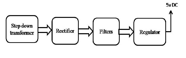 Block Diagram:
 video: