No products in the cart.


This project proposes a brand new real and reactive power coordination controller for a Unified Power Flow Controller (UPFC). The fundamental control for the UPFC is such that the series converter of the UPFC controls the transmission line real/ reactive power flow and the shunt converter of the UPFC controls the UPFC bus voltage/shunt reactive power and the DC link capacitor voltage. In constant state, the real power demand of the series converter is offered with the aid of the shunt converter of the UPFC. To prevent instability/lack of DC link capacitor voltage for the duration of transient conditions, a new real power coordination controller has been designed. The need for reactive power coordination controller for UPFC arises from the fact that excessive bus voltage (the bus to which the shunt converter is hooked up) excursions occur throughout reactive power transfers. A brand new reactive power coordination controller has been designed to limit excessive voltage excursions throughout reactive power transfers.
This project provides continuous power flow improvement in transmission line using line correction without manual capacitive bank loading. A UPFC controller provides power flow improvement in transmission line correction and peak current limiting for a switch-mode power converter of any topology (buck, boost or buck-boost), without having to directly sense inductor current.
The UPFC control technique involves using a piecewise-polynomial analog computer (AC) to compute power transistor on-times in accordance with separate polynomial transfer functions for power-factor control and peak-current-linking using as inputs current representations of line input voltage (VLN), load output voltage (VLD), and long-term current demand (VCD).
A conduction cycle is initiated by sensing when the rate of change in the inductor current reaches zero using an auxiliary winding on the current storage inductor, and terminated after the computed on-time to implement either power-factor control or peak-current-limiting.
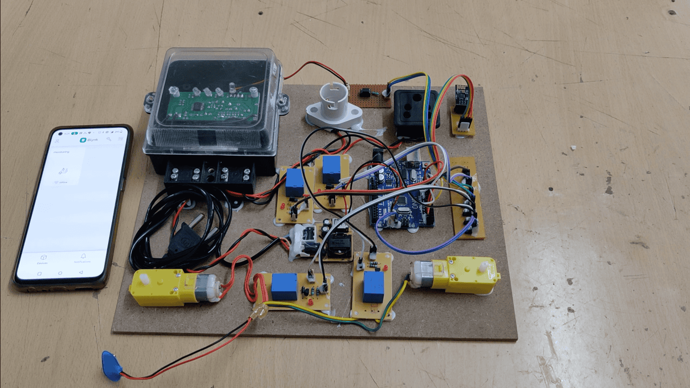
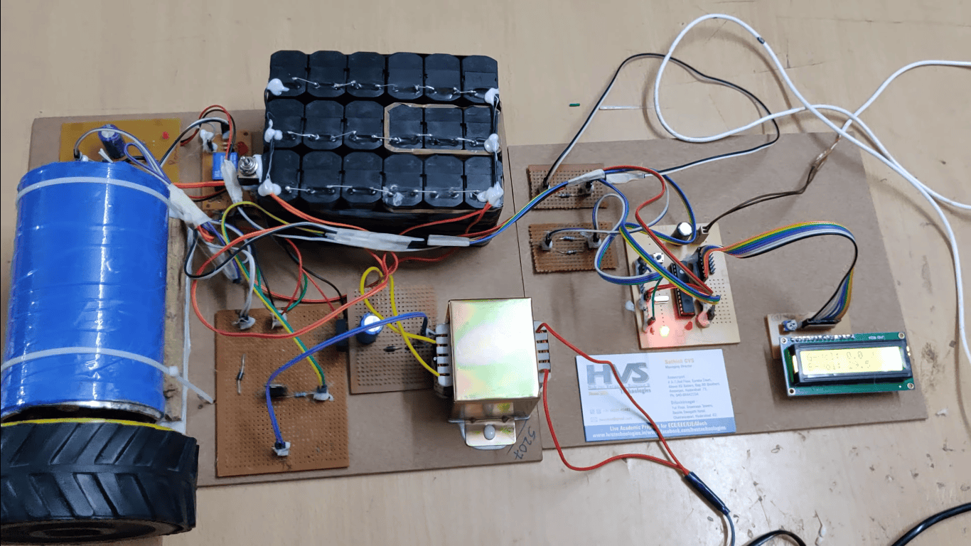
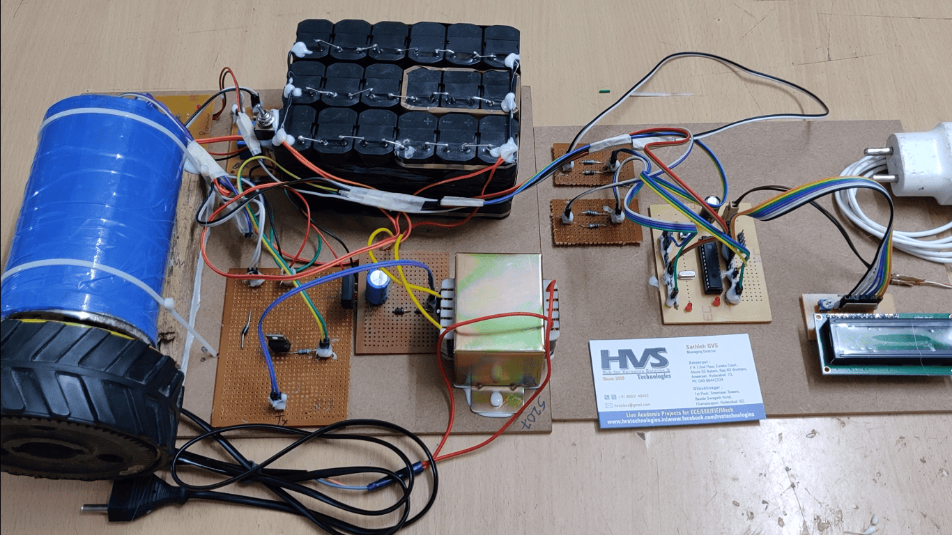
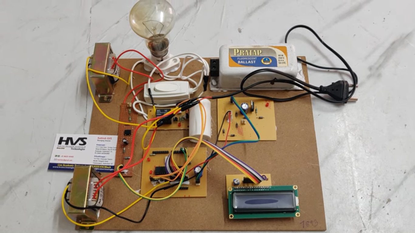
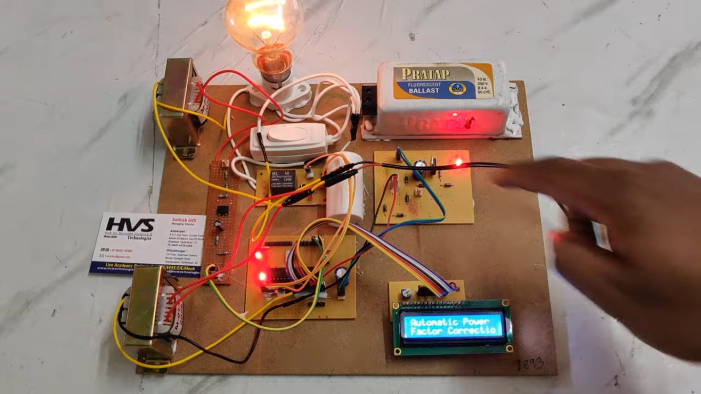
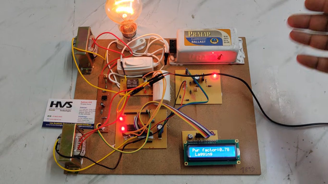
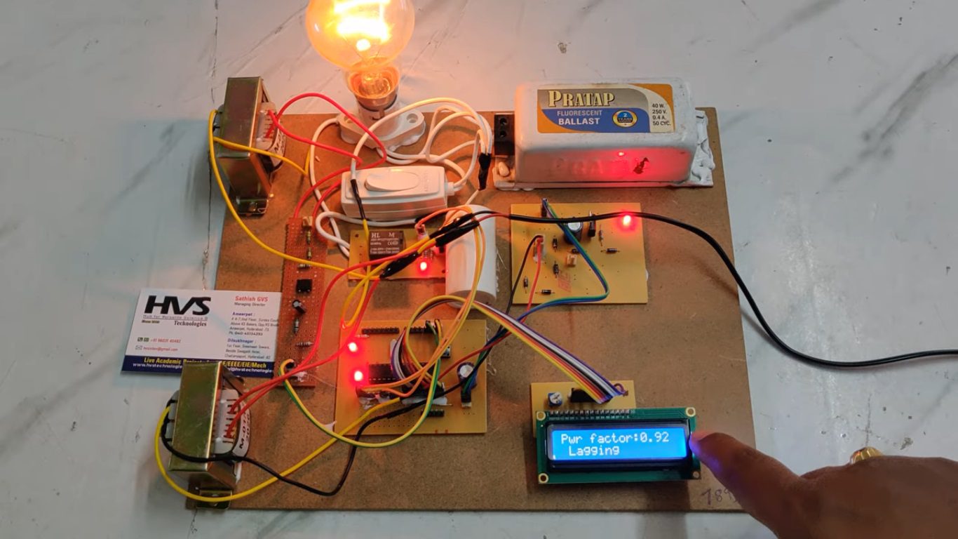
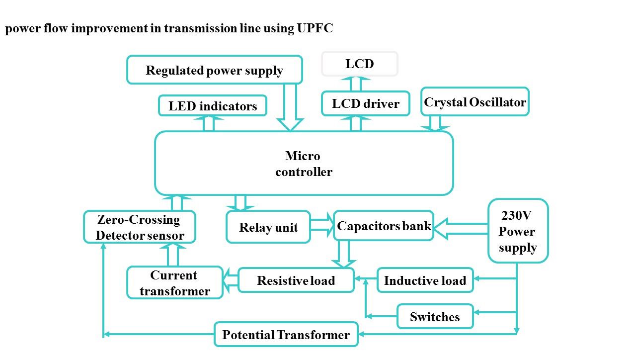
Major building blocks:
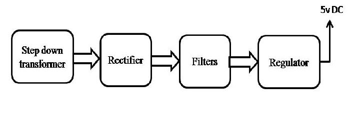
 Block Diagram:
video:
Block Diagram:
video:
- Regulated Power Supply.
- PIC Microcontroller.
- Resistive load.
- Inductive load.
- Relay bank unit.
- Current transformer.
- Potential transformer.
- Zero-crossing detector.
- LCD display.
- LED indicators.
- PIC-C compiler for Embedded C programming.
- PIC kit 2 programmer for dumping code into Micro controller.
- Express SCH for Circuit design.
 Block Diagram:
 video: