No products in the cart.


The use of green energy is becoming increasingly more important in today’s world. Therefore, electric vehicles are currently the best choice for the environment in terms of public and personal transportation. Because of its high energy and current density, lithium-ion batteries are widely used in electric vehicles. Unfortunately, lithium-ion batteries can be dangerous if they are not operated within their Safety Operation Area (SOA). Therefore, a battery management system (BMS) must be used in every lithium-ion battery, especially for those used in electric vehicles.
In this work, the purpose, functions and topologies of BMS are discussed in detail. In addition, early battery models along with the hardware and system designs for BMS are covered in a literature review. Then, an improved battery model is introduced, and simulation results are shown to verify the model’s performance. Finally, the design of a novel BMS hardware system and its experimental results are discussed. The possible improvements for the battery models and BMS hardware are given in the section on conclusions and future work.
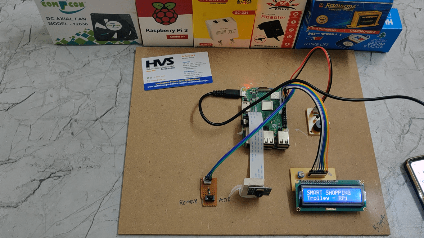
A battery management system (BMS) is proposed which is used for electronic vehicle that manages a rechargeable battery (cell or battery pack), such as by protecting the battery from operating outside its safe operating area, monitoring its state using using Raspberry pi zero.
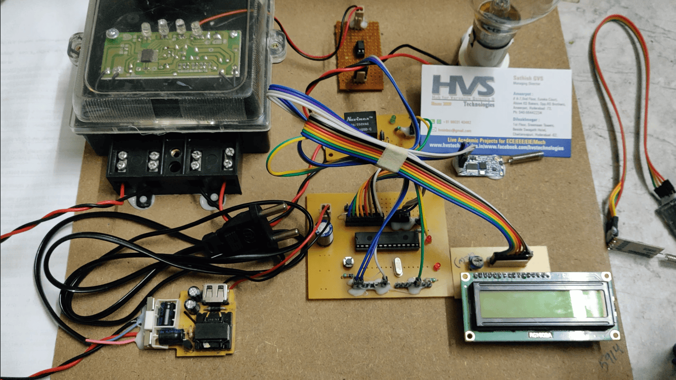
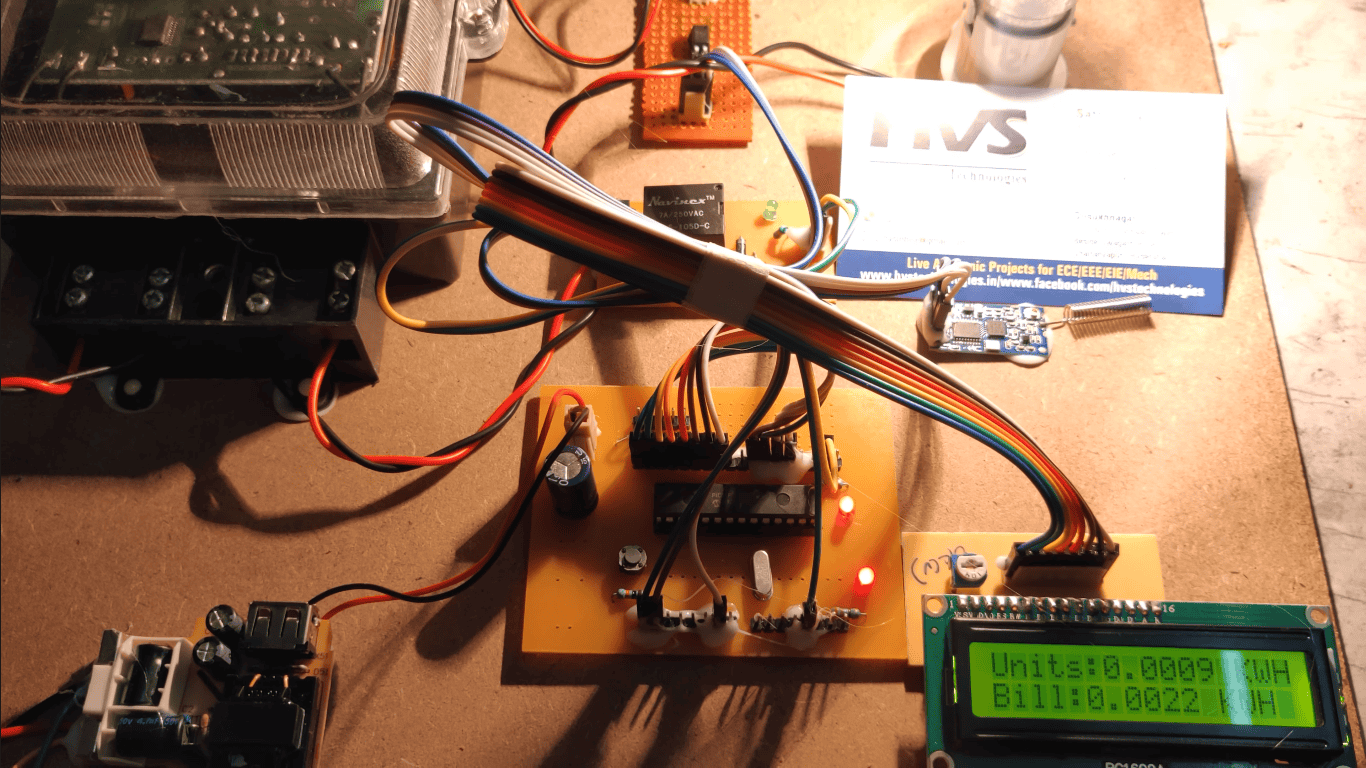
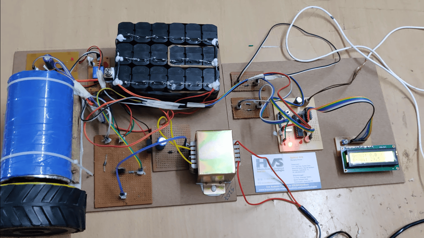
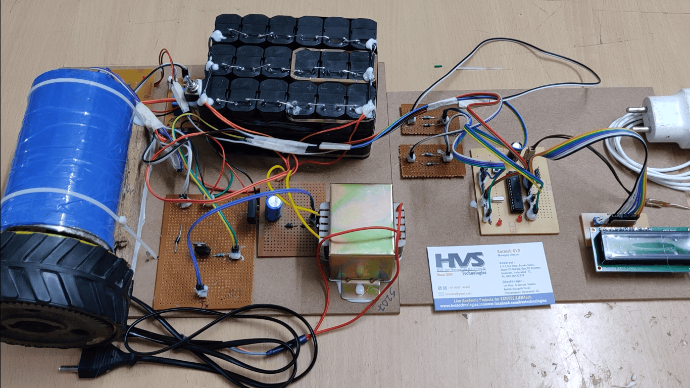
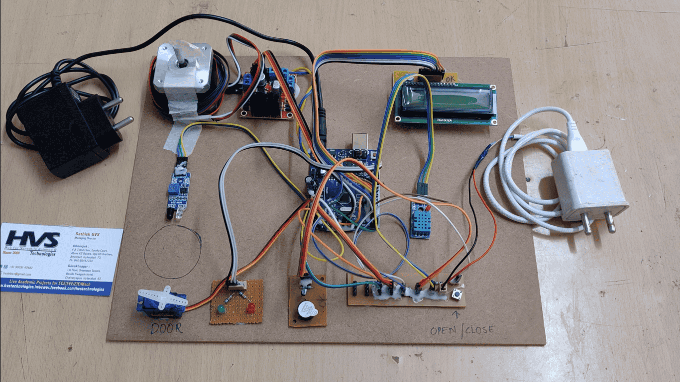
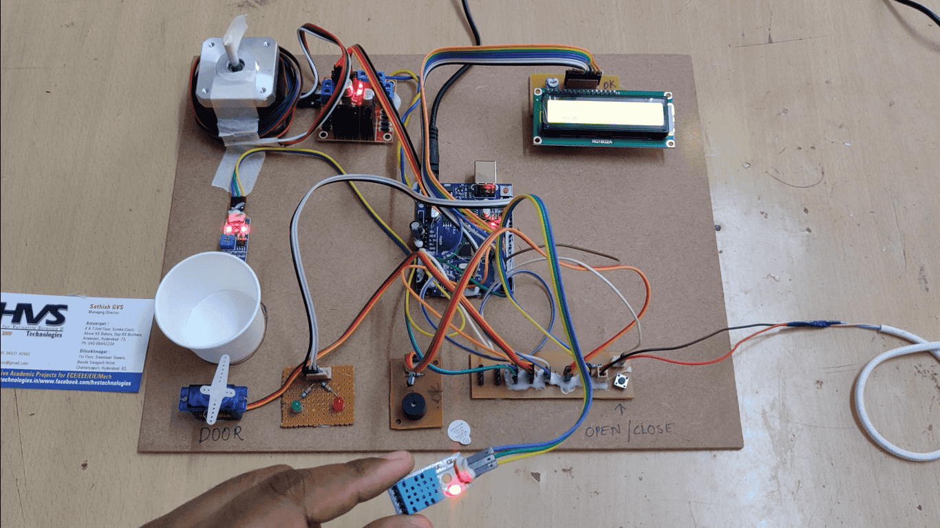
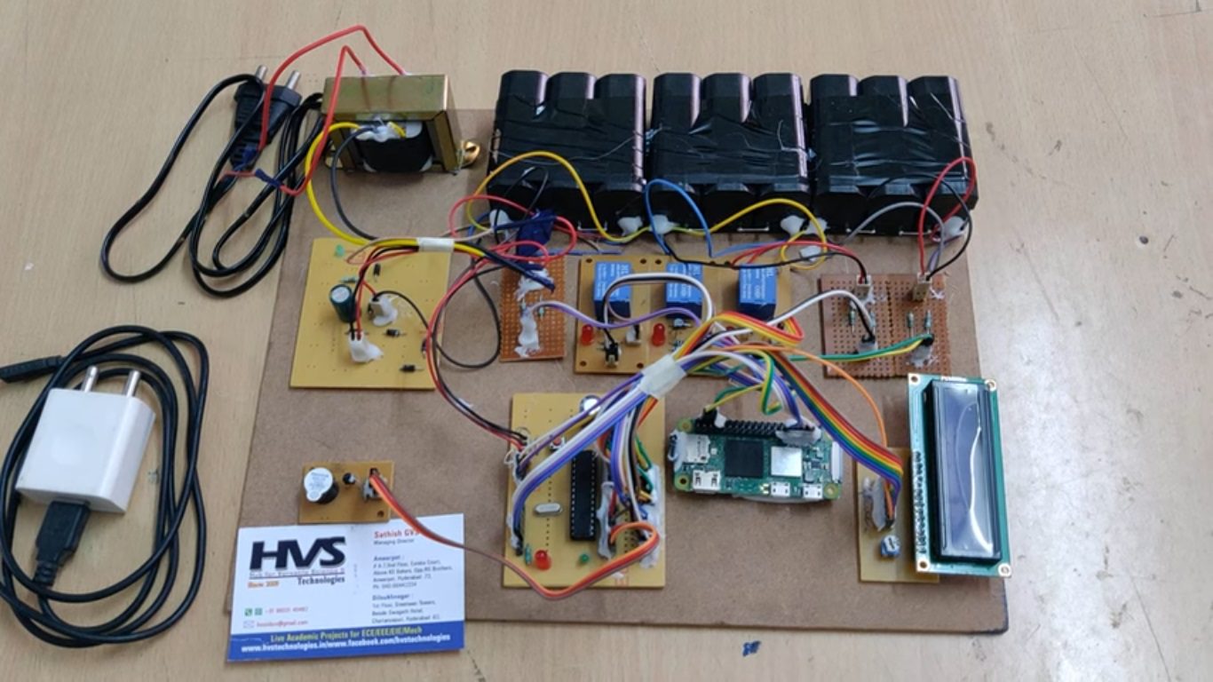
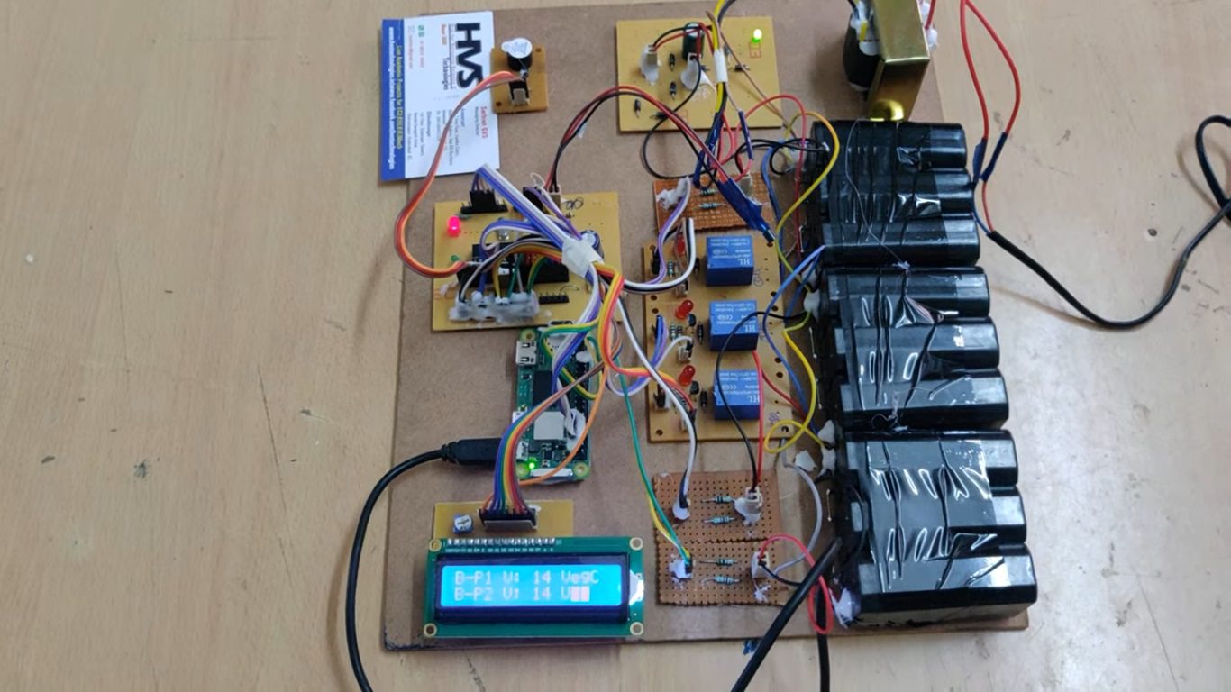
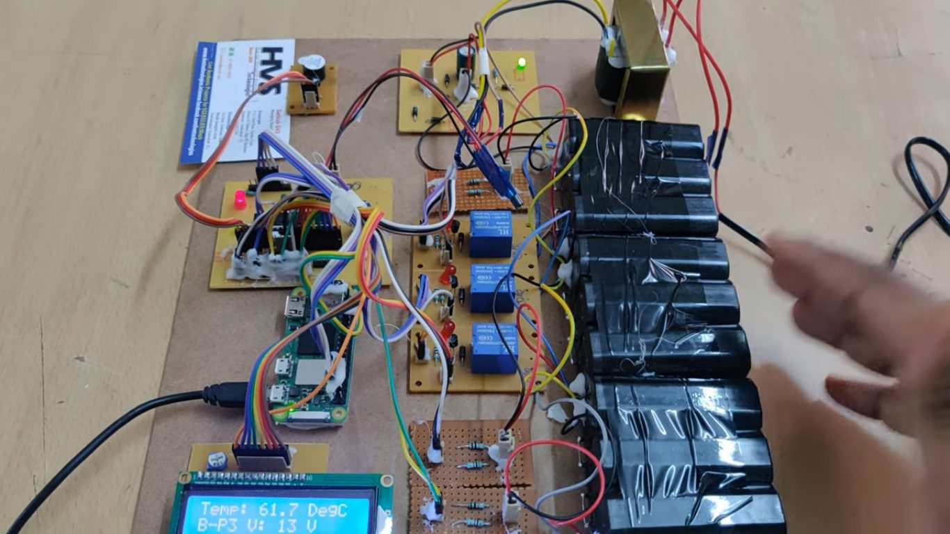
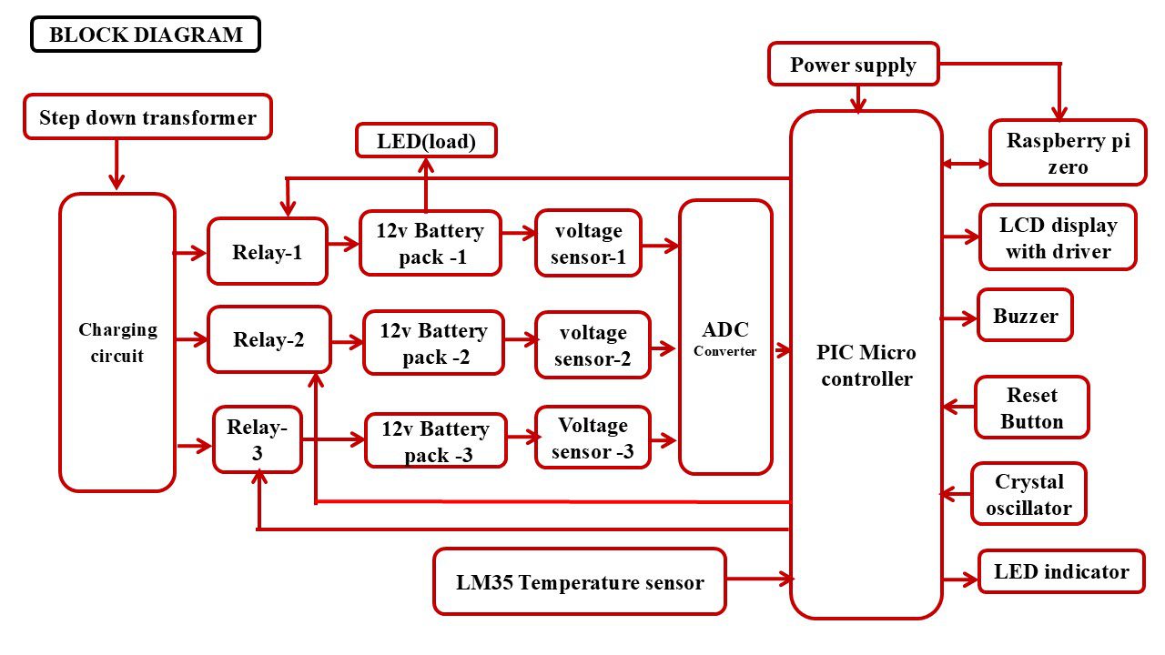
The controlling device of the whole system is Raspberry pi zero. Here PIC microcontroller works as ADC converter. Microcontroller reads the data and sends to the raspberry pi then raspberry pi process this data and send again to the pic microcontroller. The integrated modules to the controller are temperature sensor, Battery pack along with relay, Charger and LCD Module. When any of the battery pack get drained, that battery pack get charged from the charger through relay and the voltage values of each battery pack and SOC will display on LCD module as well as it displays the temperature continuously. If the temperature value crosses the set limit, then PIC microcontroller active the buzzer for alerts. The MICROCONTROLLER measures the voltage from sensor and based on that it will switch on the relay for battery charging. Here relay works as a switch to on/off the charging connection.
The major building blocks of this project are:
 video:
- Regulated power supply.
- Raspberry pi zero.
- PIC Microcontroller.
- Temperature sensor.
- Voltage sensor.
- Buzzer.
- Battery pack
- Relay.
- Charging Circuit.
- LCD display.
- LED Indicators
- Crystal oscillator
- Reset button.
- Raspbian OS and python language.
- PIC-C compiler for Embedded C programming.
- PIC kit 2 programmer for dumping code into Micro controller.
- Express SCH for Circuit design.
 video: