No products in the cart.


The use of green energy is becoming increasingly more important in today’s world. Therefore, electric vehicles are currently the best choice for the environment in terms of public and personal transportation. Because of its high energy and current density, lithium-ion batteries are widely used in electric vehicles. Unfortunately, lithium-ion batteries can be dangerous if they are not operated within their Safe Operating Area (SOA). Therefore, a battery management system (BMS) must be used in every lithium-ion battery, especially for those used in electric vehicles.
In this work, the purpose, functions, and topologies of BMS are discussed in detail. In addition, early battery models along with the hardware and system designs for BMS are covered in a literature review. Then, an improved battery model is introduced, and simulation results are shown to verify the model’s performance. Finally, the design of a novel BMS hardware system and its experimental results are discussed. The possible improvements for the battery models and BMS hardware are given in the section on conclusions and future work.
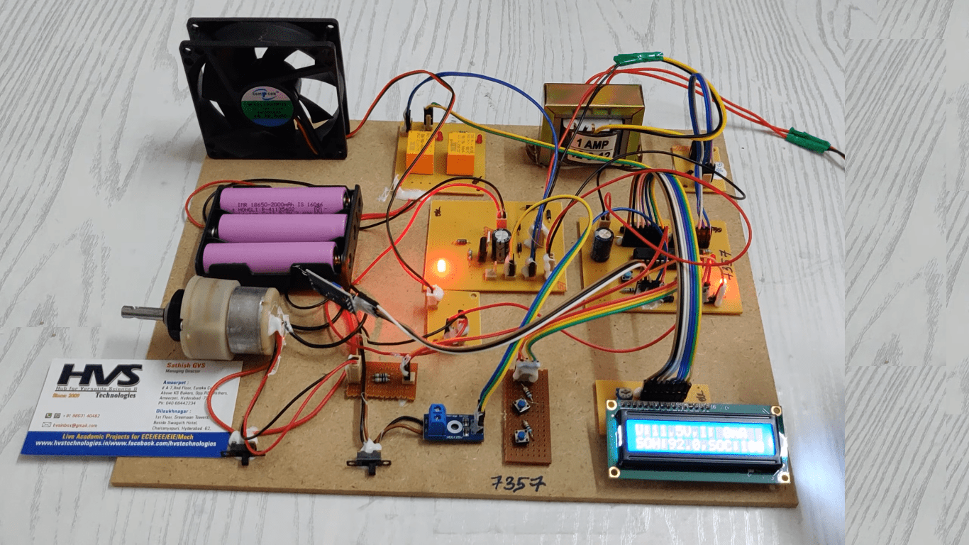
A battery management system (BMS) is proposed which is used for electric vehicles to manage a rechargeable battery (cell or battery pack), such as by protecting the battery from operating outside its safe operating area and monitoring its state using a PIC microcontroller. The BMS also estimates and monitors the State of Charge (SOC) and State of Health (SOH) of the battery to ensure optimal performance and longevity. SOC indicates the current energy level of the battery, while SOH reflects its overall condition and aging.
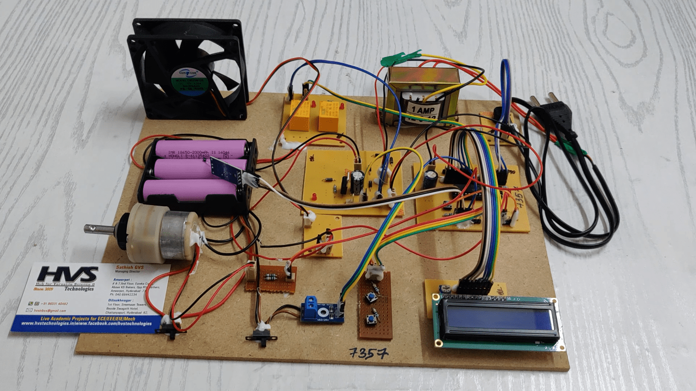
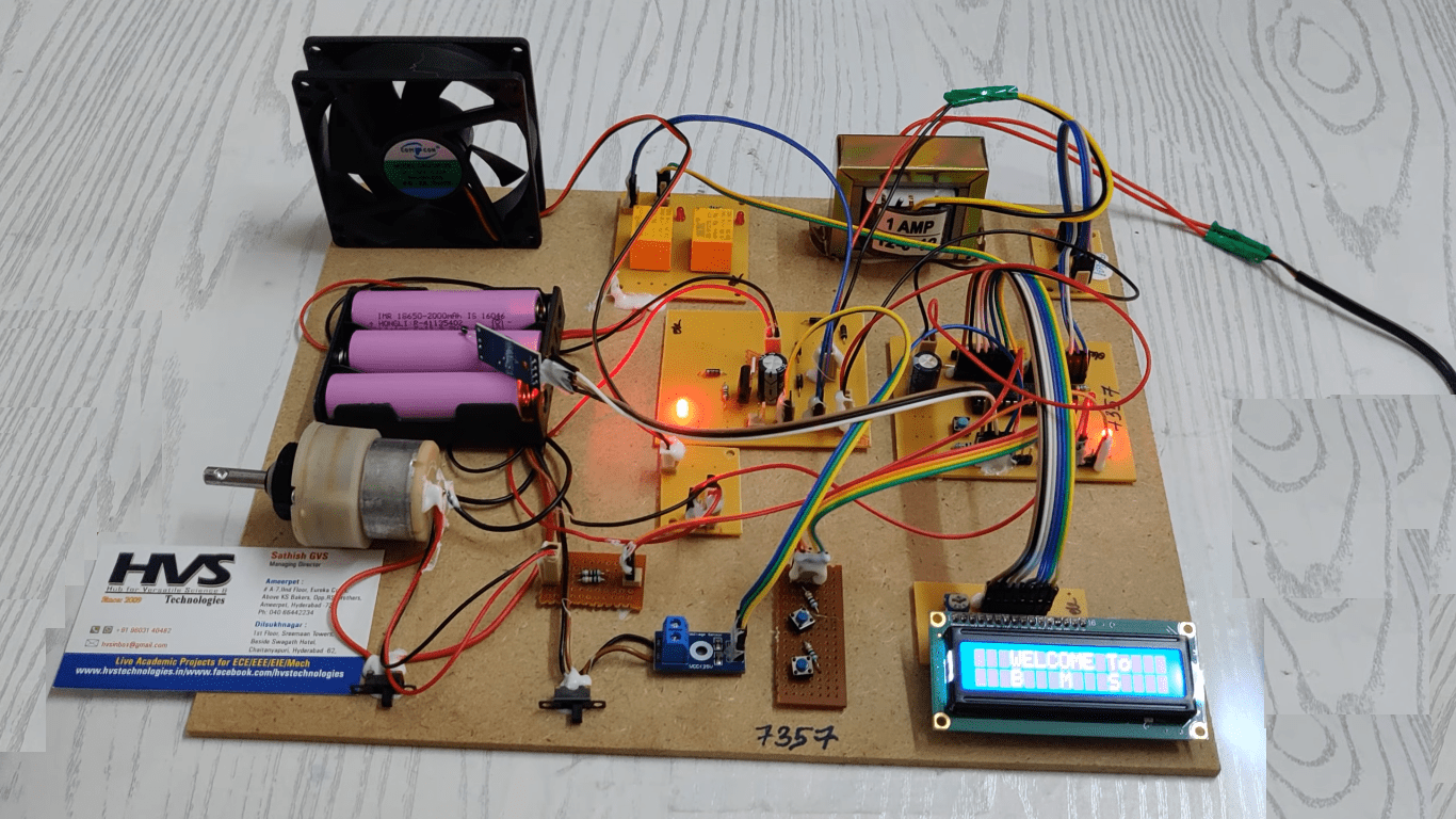
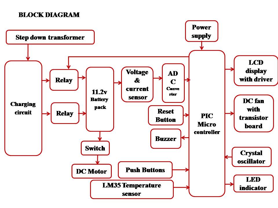
The controlling device of the whole system is a PIC microcontroller. The integrated modules to the controller are a temperature sensor, battery pack along with relays, charger, and LCD module. When the battery pack gets drained, it will be charged through relays. Two relays are used for fast and slow charging. A DC motor simulates vehicle movement. While running, the microcontroller displays voltage, current, SOC, and temperature values on the LCD module. If the temperature exceeds the preset limit, the PIC microcontroller activates a buzzer for alerts. Based on the battery voltage and SOC, the charging mode is switched between fast and slow. The relay acts as a switch to control the charging connection. This functionality is achieved by a microcontroller program written in embedded C language.
The major building blocks of this project are:
 video:
- Regulated power supply.
- PIC Microcontroller.
- Temperature sensor.
- Voltage sensor.
- Buzzer.
- Battery pack.
- Relays.
- Charging Circuit.
- LCD display.
- LED Indicators.
- Crystal oscillator.
- Reset button.
- PIC-C compiler for Embedded C programming.
- PIC kit 2 programmer for dumping code into Micro controller.
- Express SCH for Circuit design.
 video: