Skip to content

HVS-4275. A GRID VOLTAGE SENSOR-LESS CONTROL SCHEME FOR SINGLE PHASE INTEGRATED BATTERY CHARGAER.

₹14,500.00

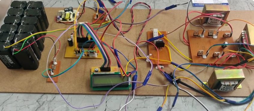
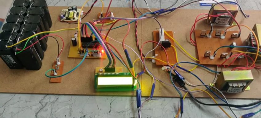
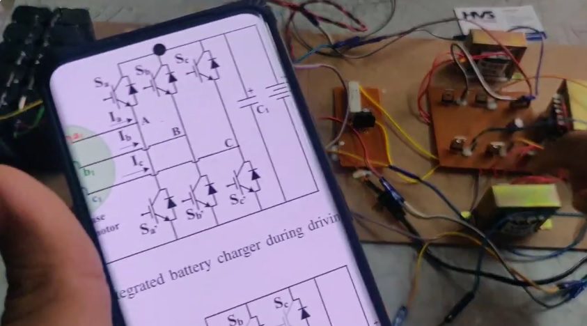
In this project, a grid voltage sensor-less control scheme for single-phase integrated battery charger is presented. In an integrated battery charger, the drive components, such as the motor and the inverter used for driving the EV, are reused for charging the battery.

Category Tags , , 
As the global adoption of electric vehicles continues to rise, integrated battery chargers play a pivotal role in shaping the future of electric transportation. In this project, a grid voltage sensor-less control scheme for single-phase integrated battery charger is presented. In an integrated battery charger, the drive components, such as the motor and the inverter used for driving the EV, are reused for charging the battery. The windings of the three-phase induction motor are used as grid interface inductances between the grid and the inverter via a diode bridge rectifier. The interleaving technique is implemented to suppress the ripple in the current drawn from the grid. In the conventional control schemes for battery chargers, there is a need for grid voltage sensing in order to draw currents from the grid at the unity power factor. However, the proposed sensor less scheme eliminates the need for sensing AC grid voltage to maintain a unity power factor. Hence, reducing the cost of the electric vehicle significantly by eliminating the need for a voltage sensor to sense the grid voltage.            

Objectives:
  1. Developed a control algorithm on the PIC16F72 microcontroller to regulate the charging process based on the sensed battery voltage and current, without requiring a dedicated grid voltage sensor.
  2. Implemented a voltage sensor interface to accurately measure the battery voltage and current, ensuring precise control of the charging process.
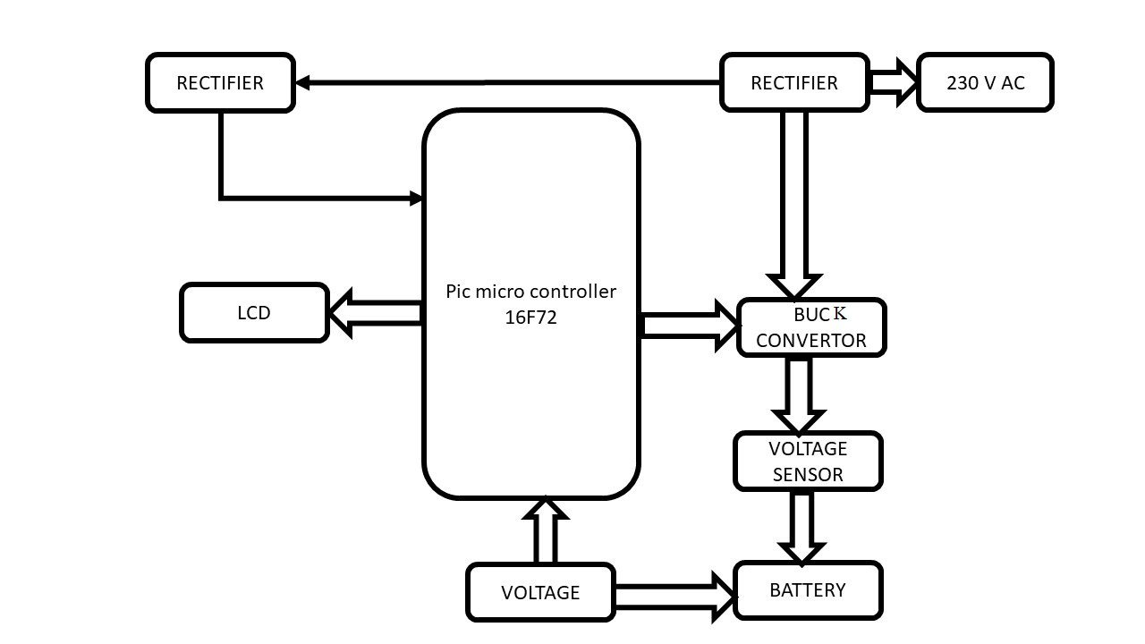
  3. Integrated a buck converter and rectifier circuit to convert the AC grid voltage to DC, with one rectifier serving as a power rectifier for the buck converter and the other for general rectification purposes.
  4. Displayed relevant information such as charging status, battery voltage, and current on an LCD screen for user monitoring and feedback.
       

The major building blocks of this project are:
  • PIC16F72
  • 2 Voltage sensors.
  • Buck-converter.
  • 2 Rectifiers.
  • Battery.
  • LCD display.
       

Software’s used:  
  1. Express PCB.
  2. PIC C Compiler.
  3. Express SCH circuit design.
           

Block Daigram:


video: