No products in the cart.


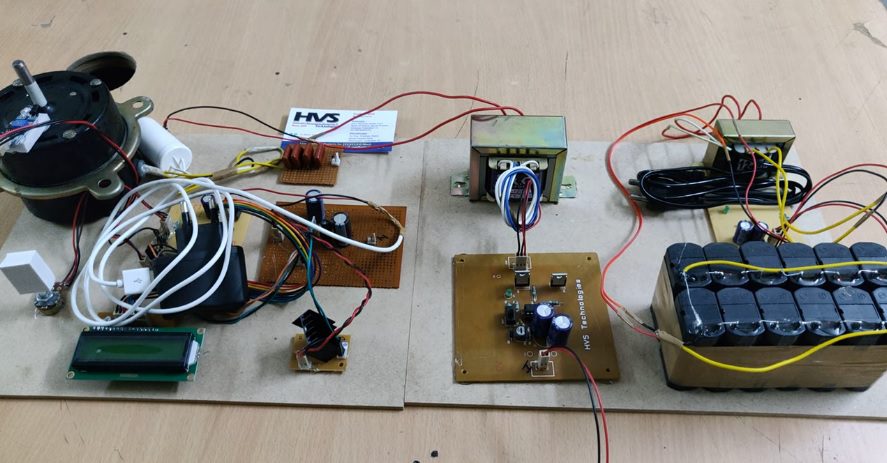
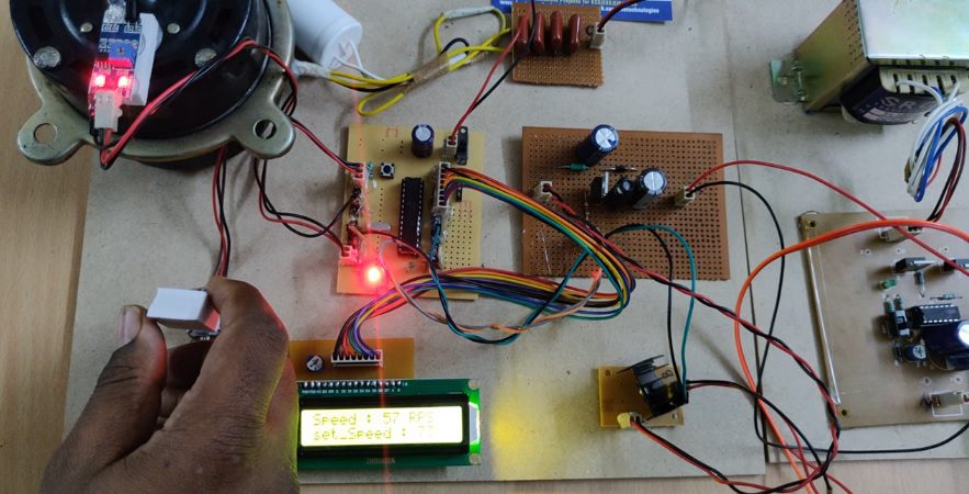
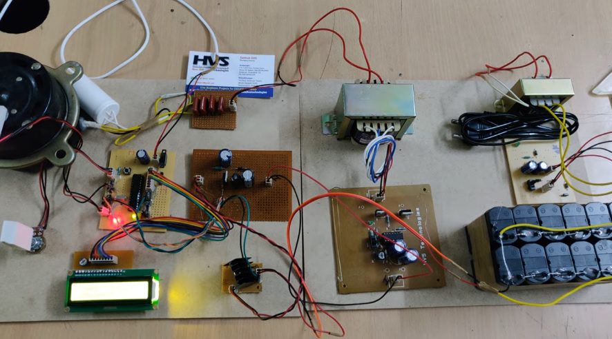
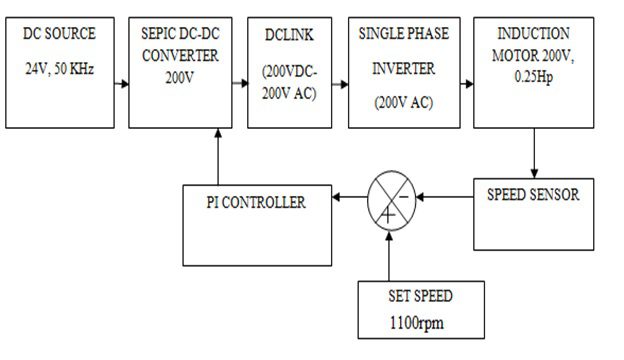
Now, a day, converter topology plays a vital role in power electronics application. The switching stress and voltage gain can be improved to a great extent. The proposed converter employs a SEPIC converter and a coupled inductor, with low duty ratios and high turns ratios generally needed for the coupled inductor to achieve high step-up voltage conversion. The basic inductor has been replaced by a coupled inductor increases the voltage gain and secondary winding of the coupled inductor in a series with a switched capacitor for further increasing the voltage. The input voltage is 24V and the output voltage is equal to 200V. Steady state operation and design procedure is presented. This paper is focusing on implementing PI controller to control the speed of the AC motor.
The major features of this project are:
 video:
- DC-DC convertor (SEPIC).
- Interfacing speed sensor to microcontroller.
- Control the speed of induction motor using PIC microcontroller.
- Conversion of AC supply to DC supply using single phase full bridge inverter.
- Set the speed value of induction motor using pot.
- SEPIC converter.
- Single phase inverter.
- Induction motor.
- Speed sensor.
- PIC Controller.
- PIC-C compiler for Embedded C programming.
- PIC kit 2 programmer for dumping code into Micro controller.
- Express SCH for Circuit design.
 video: