Skip to content

HVS-3096. Advanced User Controlled Roof Top Antenna Signal Tracking System With Geared DC Motor

5,500.00

The Advanced User Controlled Roof Top Antenna Signal Tracking System with Geared DC Motor is designed to improve television and wireless signal reception by automatically aligning a rooftop antenna toward the strongest signal source.

The Advanced User Controlled Roof Top Antenna Signal Tracking System with Geared DC Motor is designed to improve television and wireless signal reception by automatically aligning a rooftop antenna toward the strongest signal source. The system uses a PIC microcontroller as the main control unit and employs IR transmitter and IR receiver modules for signal detection and tracking. Based on the received signal strength, the microcontroller controls a geared DC motor through a motor driver circuit to rotate the antenna in the desired direction for optimal signal reception. The system also incorporates an LCD display to provide real-time status information, LED indicators for operational monitoring. A regulated power supply ensures stable operation of all components. This project reduces the need for manual antenna adjustment, improves signal quality, and provides a reliable, user-friendly solution for rooftop antenna positioning and tracking applications.    

Main features of this project:  

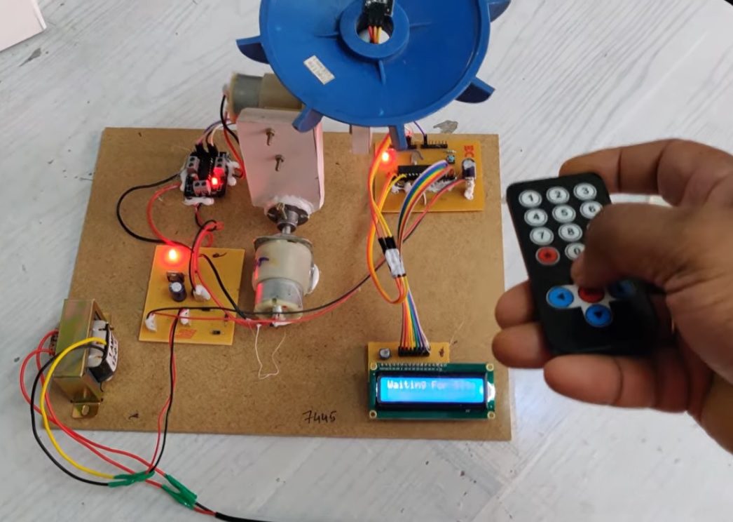
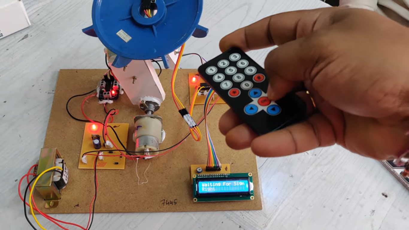
 Automatic antenna alignment for maximum signal reception.

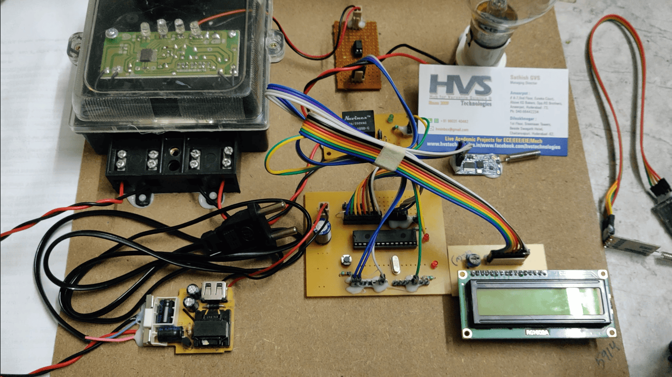
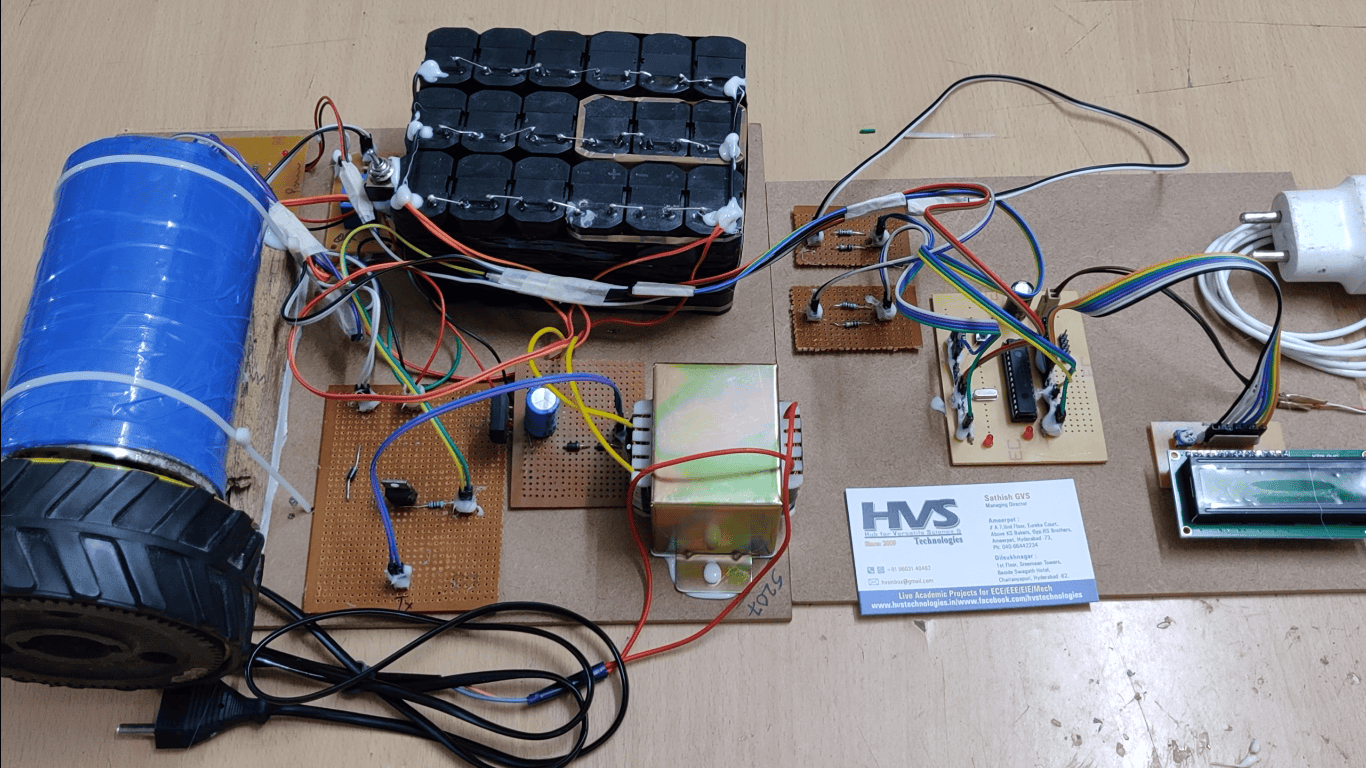
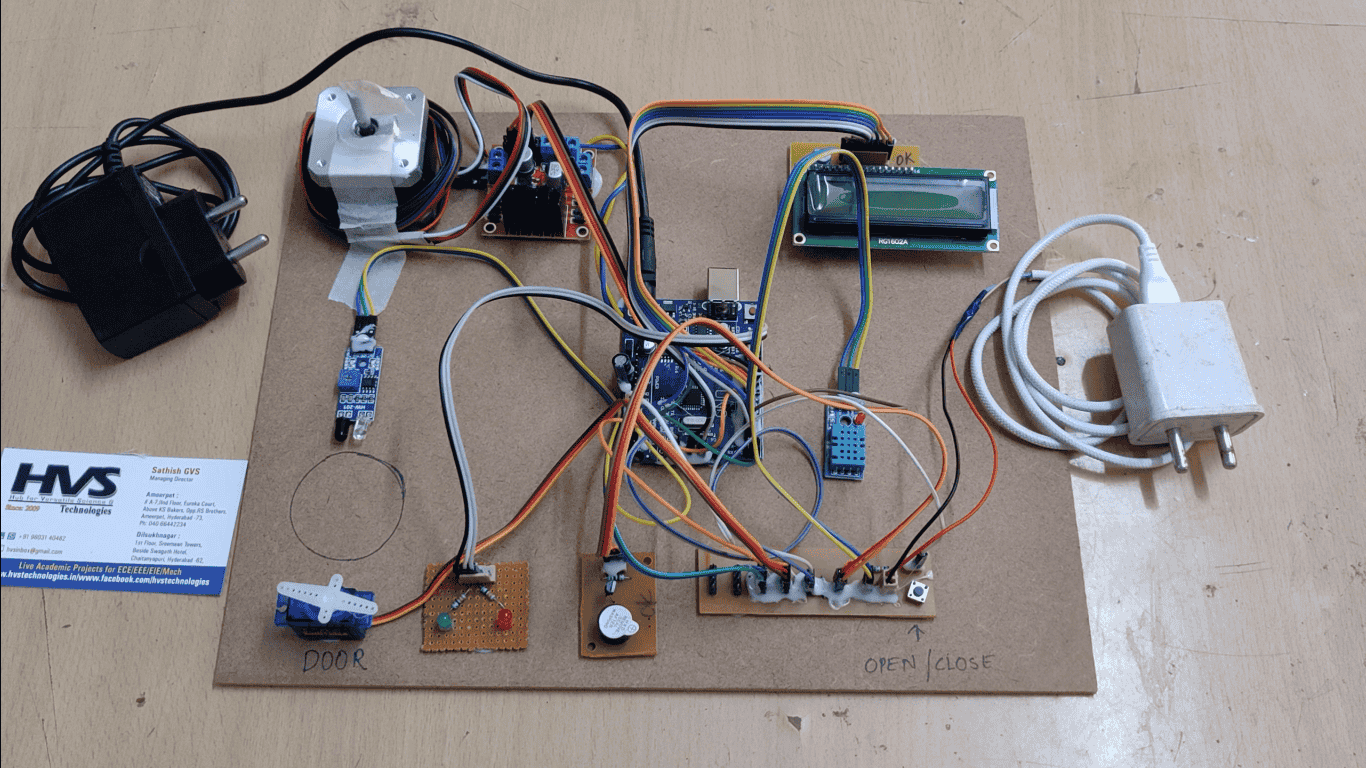
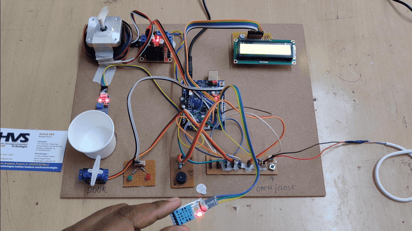
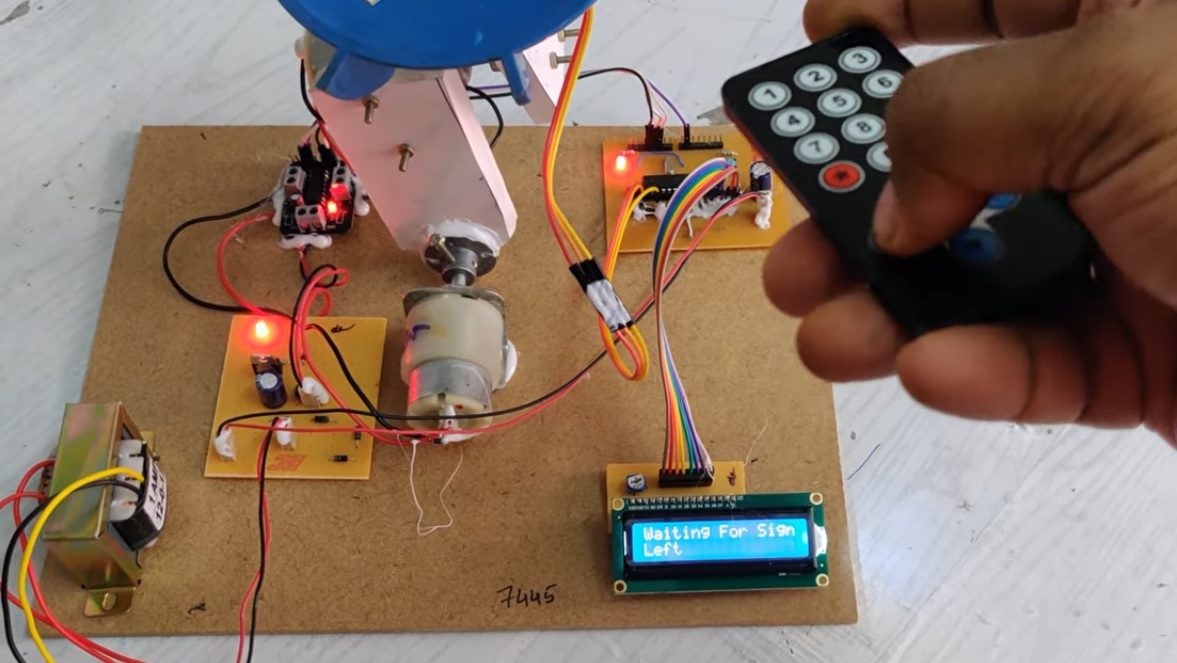
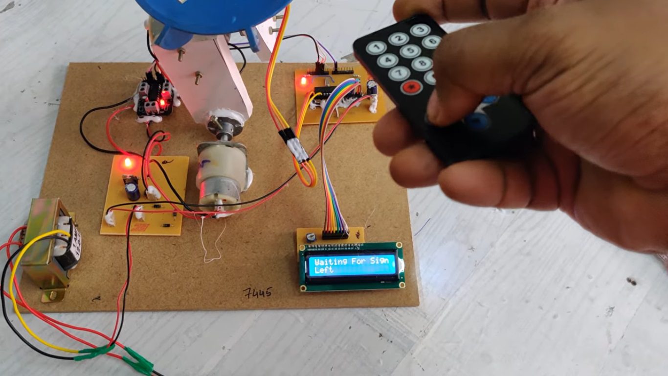
 PIC microcontroller-based intelligent control system.

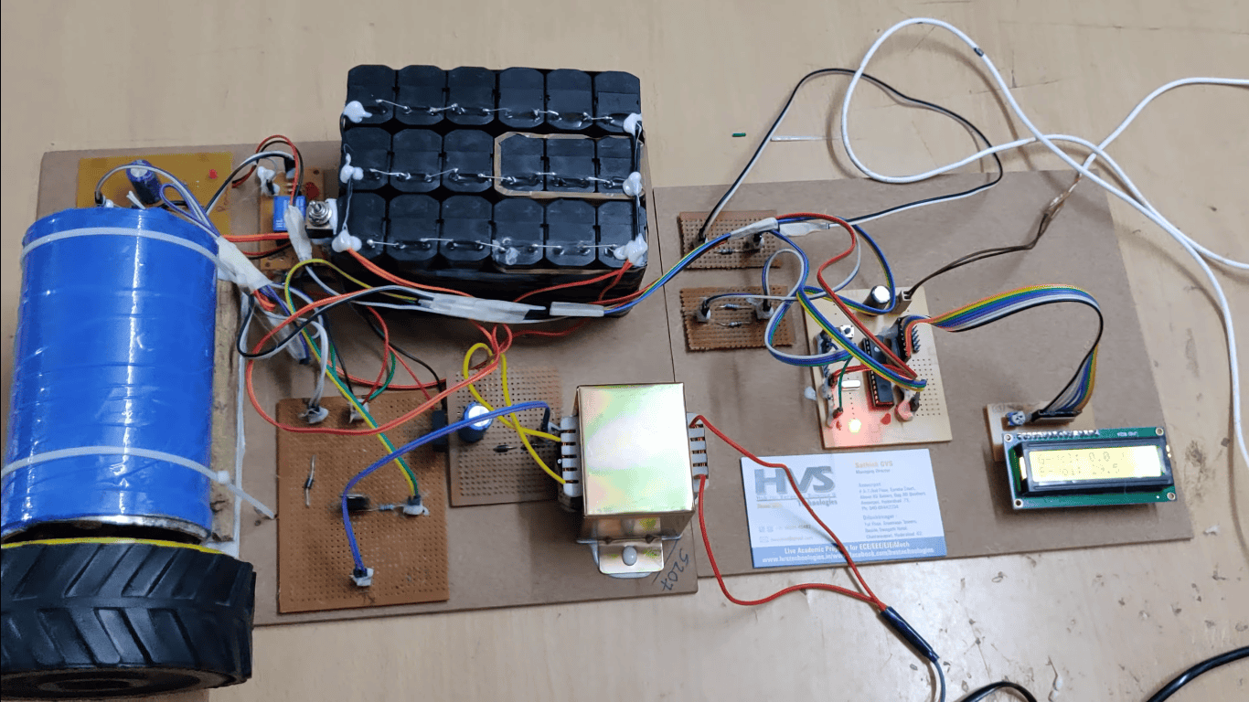
 Geared DC motor for precise antenna rotation and positioning.

 IR transmitter and receiver for signal tracking and control.

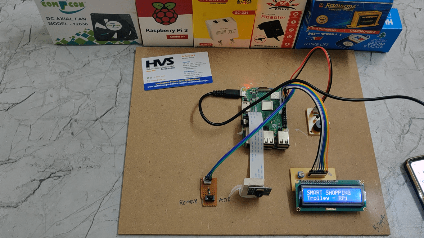
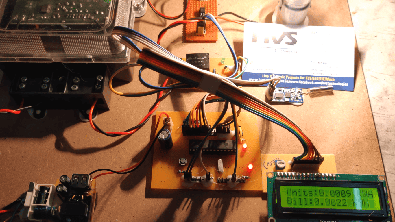
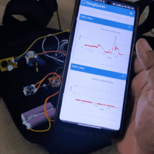
 Real-time antenna status display on LCD screen.

 LED indicators for system operation and signal status.

 User-controlled antenna positioning capability.

 Stable operation using a regulated power supply.

 Reduces manual effort and improves signal quality.

 Compact, reliable, and low-power design.

 Suitable for TV, radio, and wireless communication antenna applications.  

Major blocks present in this project:
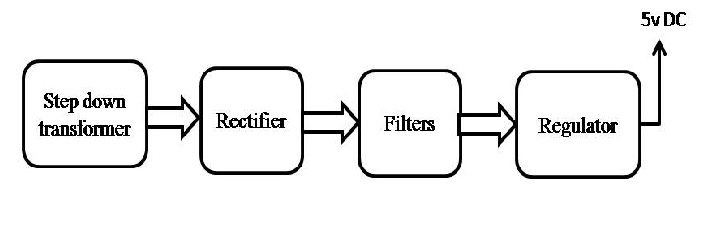
  1. Regulated Power supply.
  2. PIC microcontroller.
  3. LCD display.
  4. DC Motors with L283d.
  5. IR T x.
  6. IR Rx.
  7. Antenna Arrangement.
  8. Crystal Oscillator.
  9. Reset Button.
  10. LED indicator.
    Software’s used in this project:
  1. PIC Compiler for Programming.
  2. Express SCH for Circuit design.
    Regulated power supply:


Block Diagram:    

video: