Subtotal ₹58,500.00


The main aim of the project is to design the Bi-Directional DC-DC buck-boost converter and its modulation technique.
The bidirectional isolated DC-DC converter has attracted more and more attentions and has a wide potential application in the fields of electrical vehicle charger, solid state transformer, energy storage system because of the advantages of good soft-switching operation and wide voltage conversion range, and so on.
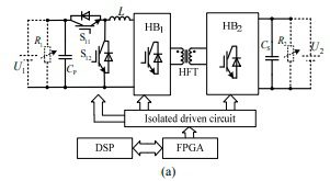
The proposed bidirectional buck-boost current-fed isolated DC-DC converter (B3CFIDC), including one bridge arm composed of the switches S11 and S12, inductor L, H-bridge converter (HB1), H-bridge converter (HB2) and a high frequency isolation transformer (HFT). L1k and n are the leakage inductor and winding ratio of HFT, respectively. L, HB1, HB2 and HFT constitute a standard current-fed isolated DC-DC converter. It can only achieve boost operation when power is transferred from high potential to low potential and only achieve buck operation in reverse direction.
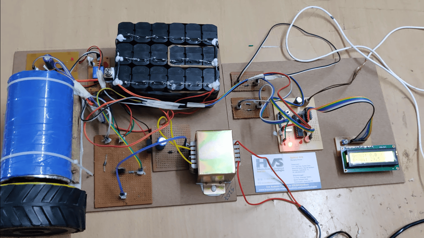
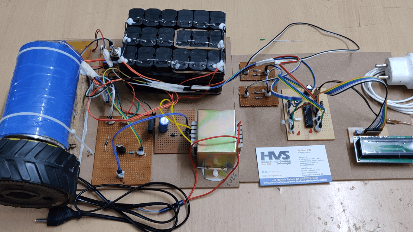
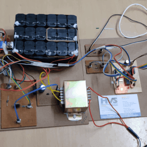
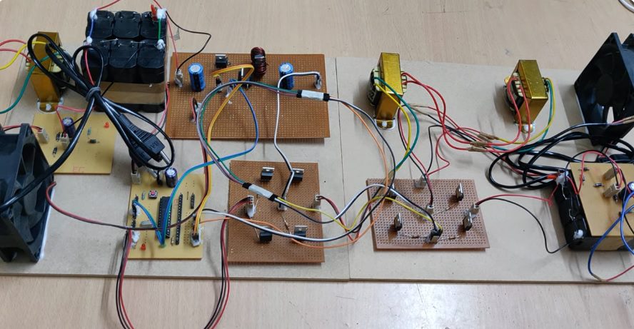
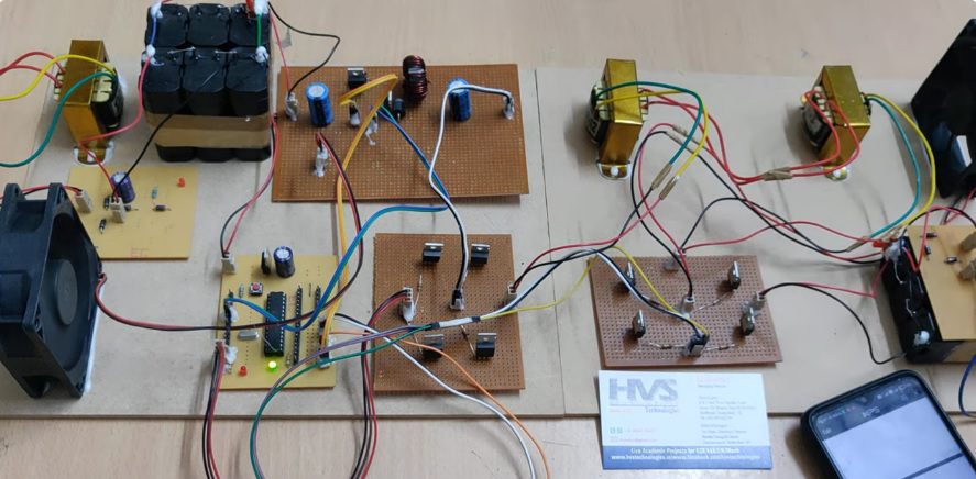
In this project, firstly we have Regulated power supply section on both the ends of the main circuit just to charge up the batteries. The DC from the charged Battery 1 flows to Bi-directional Buck-Boost Converter (B3C). The PIC Microcontroller sends the pulse input to the B3C circuit. The DC from that circuit goes to the first H-Bridge Circuit (HB1) which gives AC that is then given to the transformer circuit which is called as High Frequency 1:1 Transformer (HFT). The AC from that circuit goes to second H-Bridge circuit (HB2) which acts as a rectifier, so we get a DC here that is given to a load and battery in parallel. In this circuit, the first battery is a High Potential one and Last battery is a low potential one. In our presentation, we use 2 DC Fans of rating 12V, 100MA but in reality, battery can be kept as load. When power is transmitted from High potential to low potential which acts as Buck Converter and when power is transmitted from low potential to high potential, acts as Boost converter.
The PIC Microcontroller takes care of voltage measurement along with current which we get from low potential battery to high potential battery and vice-versa. The Microcontroller system takes care of modulation for B3C circuit. We are going to control these 2 MOSFETS whether they should act as Buck or Boost Converter.
When we switch ON the circuit, LED indication shows that Buck mode is turned on. In this case, we can sense that fan 2 is running. When it’s in Boost converter, Green LED glows and then first fan gets ON. When both the circuits are turned ON (Buck and Boost) at a time, there is a chance of MOSFET shift. Therefore, it’s better to use one mode at a time.
We use 2 MOSFETs here IRF540 of rating 36V, 18A and B3C is of 200MA which bucks the voltage along with current.
Components used:
 video:
- Regulated power supply.
- PIC Microcontroller.
- 1 Transformer.
- Rechargeable batteries.
- Charging circuit.
- DC-DC boost converter.
- H-bridge inverter.
- PIC-C compiler for Embedded C programming.
- PIC kit 2 programmer for dumping code into Micro controller.
- Express SCH for Circuit design.
 video: