No products in the cart.


DC voltage is converted from one voltage level to another using a DC-to-DC converter. Applications of DC-to-DC converter includes self-regulating power supplies, current sources to drive solid state lighting applications, advanced datacom and telecom systems, appliance control, DC motor drives, aircraft, etc. But controlling of this converter is vital task in conversion of power. Focus of this paper is to model a controlling system for buck converter which controls output of buck converter and keeps it constant instead of changing circuit parameters, load and input supply of the buck converter. The pulse width modulation (PWM), voltage mode control, PWM linear mode control with proportional controller (P), proportional integral controller (PI), and proportional integral derivative controller (PID) are some of the controlling methods are used for dc-dc converters.
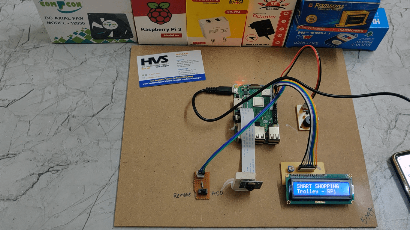
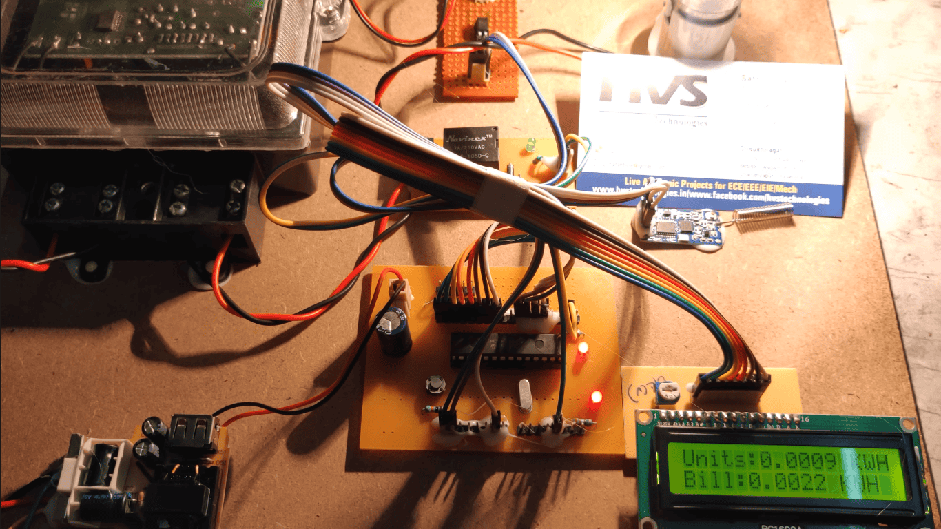
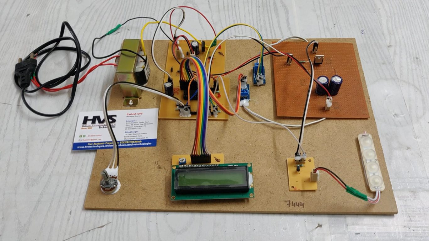
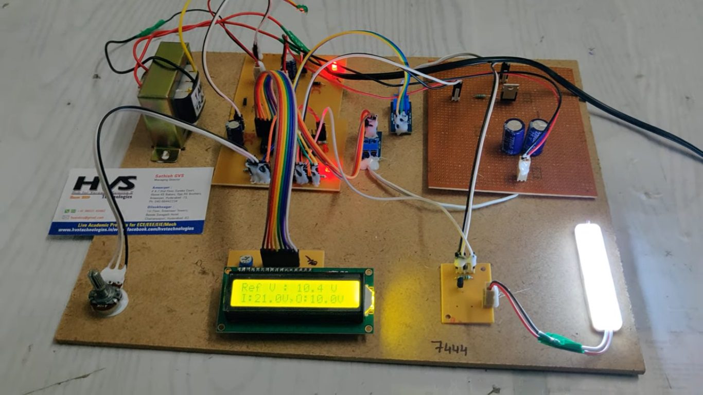
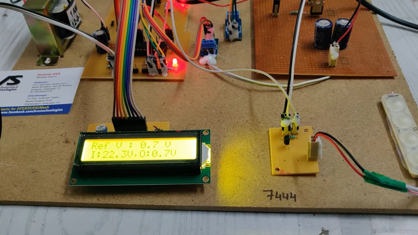
In this system, we use buck converter which steps down the input voltage which is used to switch ON the DC load i.e., LEDs in this case. These LEDs are connected to Microcontroller which measures voltage. The calculated voltage is displayed on LCD.
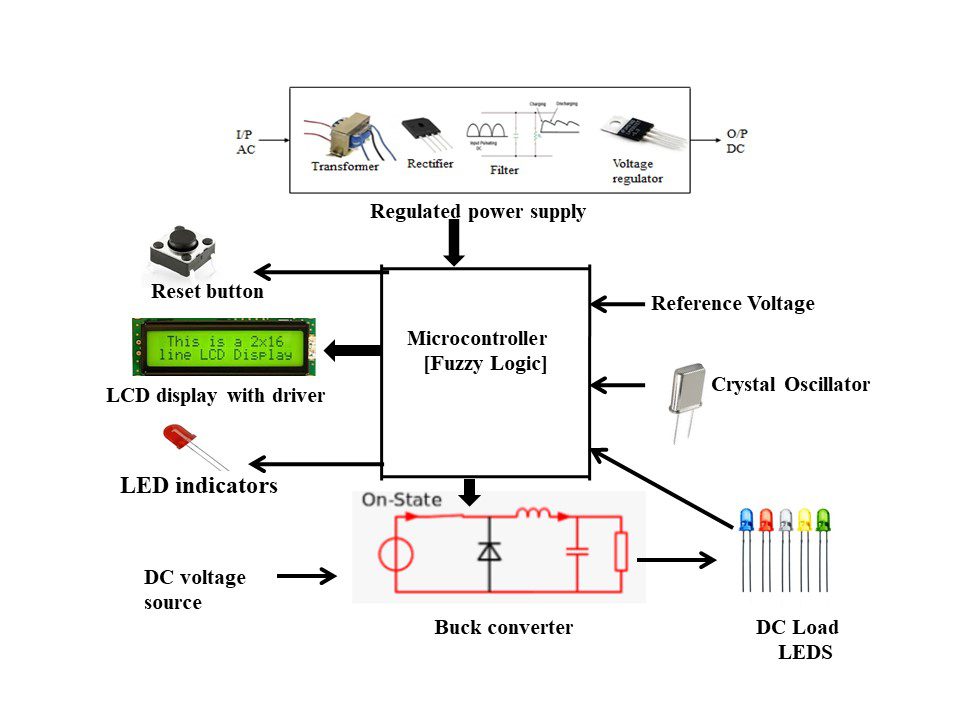
The main building blocks of the project are:
 Block Diagram:
video:
Block Diagram:
video:
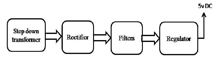
- Regulated Power Supply.
- Fuzzy logic controller.
- LCD display.
- Reference Voltage.
- Reset button.
- LED indicator.
- Crystal oscillator.
- Buck converter.
- DC voltage source.
- PIC Compiler for Programming.
- Express SCH for Circuit design.
 Block Diagram:
 video: