No products in the cart.


The project aims in designing an instrument for identifying the energy tapping directly from the grid system. Energy stealing directly from the main line is the major problem in our country, especially in rural areas lot of energy is tampered and our Electricity department doesn’t have any appropriate instrument to detect exactly where the energy is looted. Therefore this project work is taken up for the benefit of state Electricity Department.
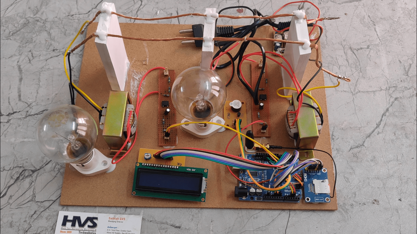
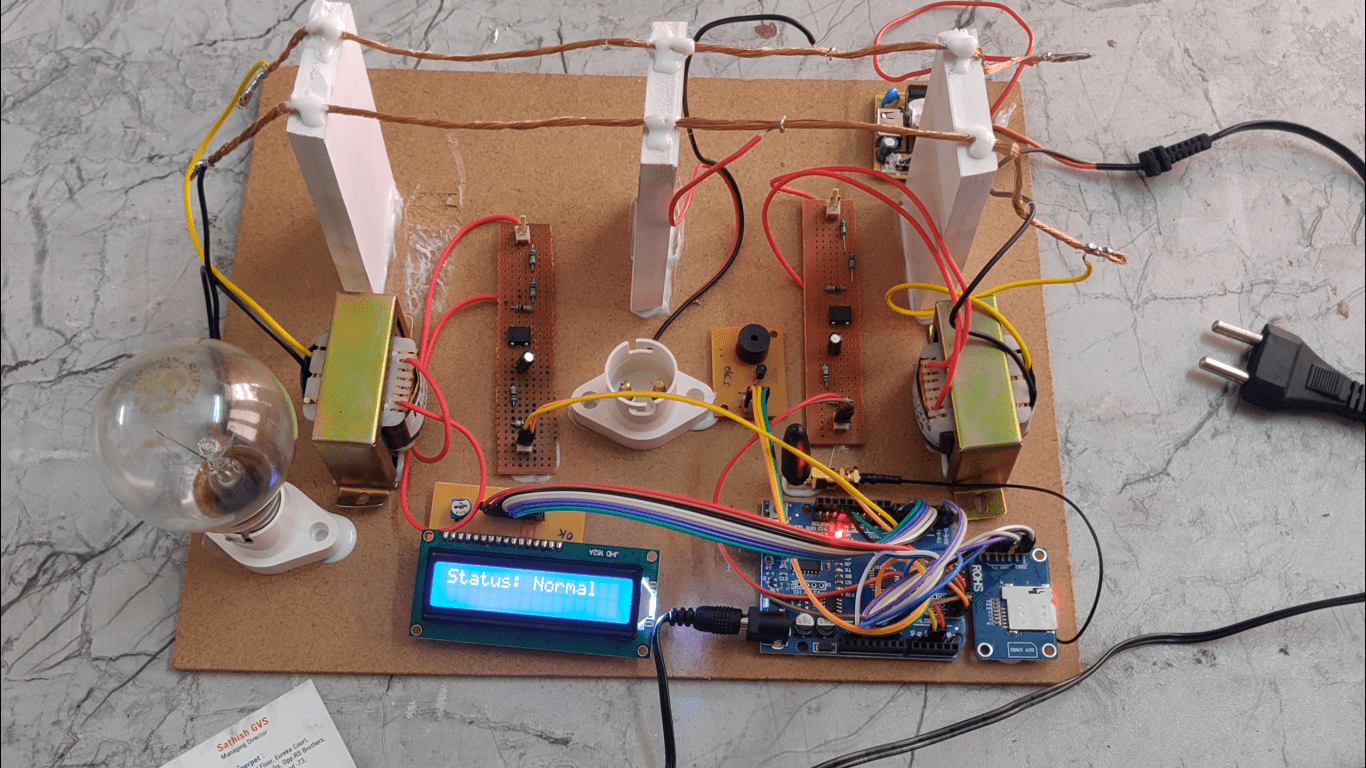
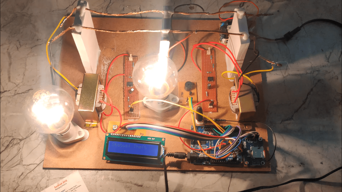
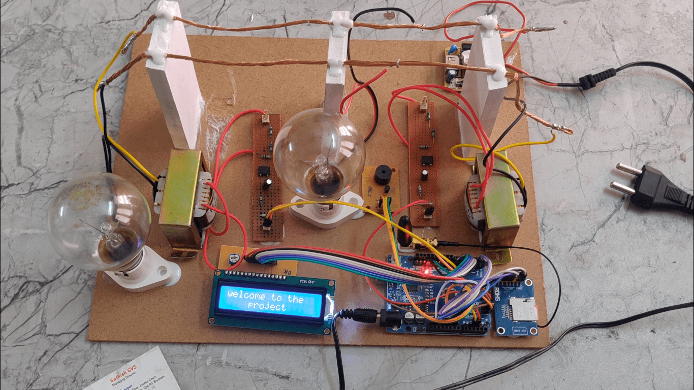
The concept involved in the system is to measure the current flowing in the energy transmission line at sensitive areas, sensitive area is defined as where the transmission lines are passing very near to a village or passing over an agriculture field and people are tapping energy to run the pump sets. At these areas the current is measured with two CT’s (Current transformers), these CT’s are arranged at either side of the sensitive area, in series with phase. Now the current flowing through the CT primary is converted into digital and is fed to microcontroller. The controller displays the current in amps, since two CT’s current is to be measured; two CT are designed with microcontroller unit. CT1, which is supposed to be installed at starting point of particular zone, can be called as master unit. The CT2 can be installed at other end of that particular zone, the current flowing through this unit CT2 is transmitted in digital form. The Arduino will receive this data and displayed onto LCD. The data acquired through wired is compared with master CT1 output and difference is displayed in separated row. The current flowing through both the CT’s is almost equal, line loss is considered, whenever the energy is tapped between the two CT’s, more current is passed through first CT, and the system is programmed such that when the difference is more than3-4% approximately, system energizes the alarm automatically and using relay to on and off the theft. If the system detects energy tapping it will send alert SMS through GSM and activate the buzzer for alerts. The status of the project will display on LCD module.
The main objectives of the project are:
 video:
- Automatic identification of energy tapping.
- Using two CTs to detect the tapping.
- Visible alerts using LCD display.
- Audible alerts using BUZZER.
- GSM based SMS alert.
- Using ARDUNIO UNO to achieve this task.
- Working of current transformer.
- Embedded C programming.
- PCB designing.
- ARDUNIO UNO
- Regulated power supply (RPS)
- Crystal oscillator
- LCD Displays
- Current transformers
- GSM module.
- Buzzer.
- LED indicators.
- Arduino IDE compiler for dumping code into Micro controller.
- Embedded C Language.
- Express SCH for Circuit design.
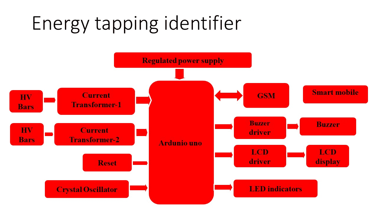
Block diagram:
 video: