No products in the cart.


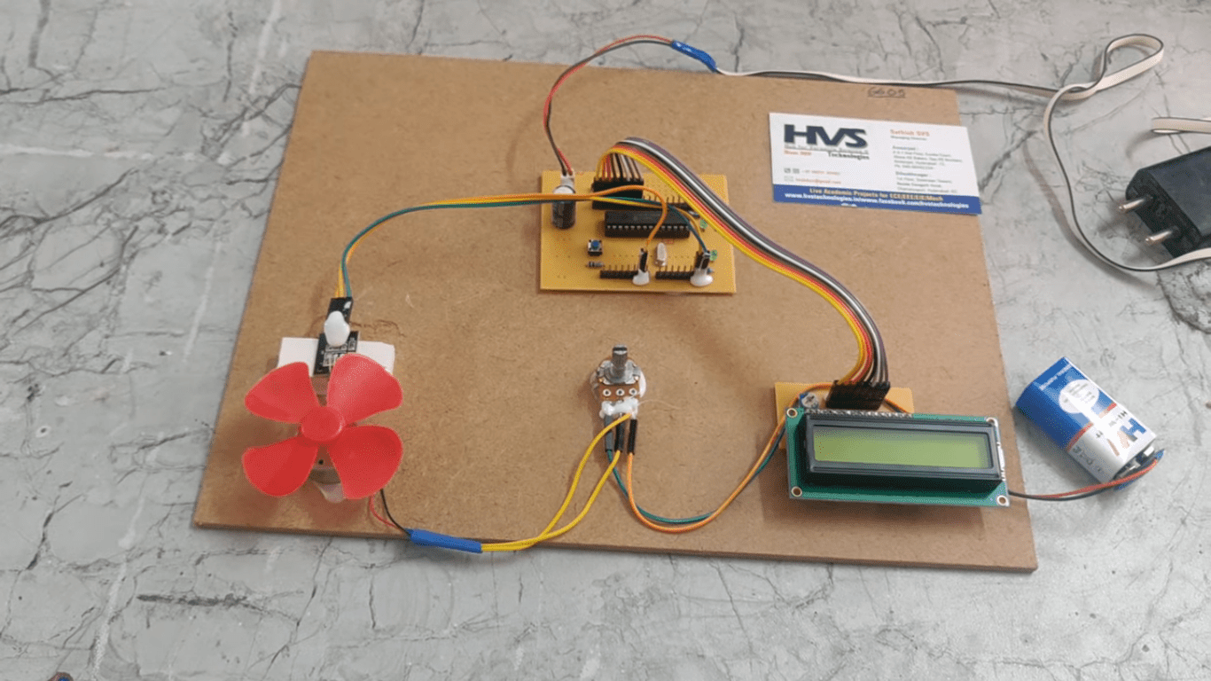
The purpose of this project is to design and construct a non-contact type of Tachometer. A tachometer (also called a revolution-counter, rev-counter, or RPM gauge) is an instrument that measures the rotation speed of a shaft or disk, as in a motor or other machine. Hall Effect sensors typically use a rotating target attached to a wheel, gearbox or motor. This target may contain magnets, or it may be a toothed wheel. The teeth on the wheel vary the flux density of a magnet inside the sensor head.
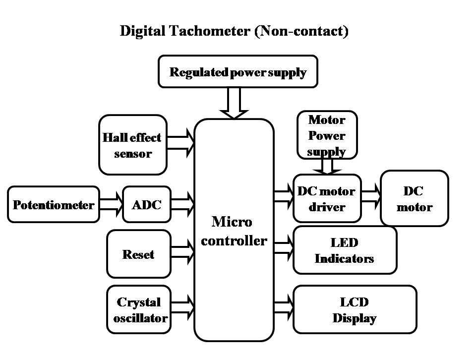
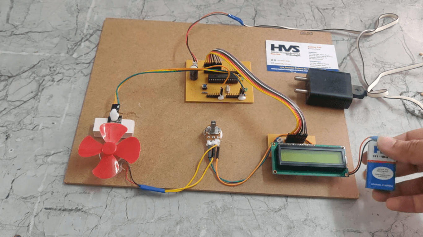
This project consists of a Hall Effect sensor connected to a microcontroller unit. The sensor signals from Hall Effect sensor are sent to microcontroller for rpm measurement. These measured final values are displayed on a LCD display connected to microcontroller.
A Hall Effect sensor is a transducer that varies its output voltage in response to changes in magnetic field. Hall sensors are used for proximity switching, positioning, speed detection, and current sensing applications.
Electricity carried through a conductor will produce a magnetic field that varies with current, and a Hall sensor can be used to measure the current without interrupting the circuit. Typically, the sensor is integrated with a wound core or permanent magnet that surrounds the conductor to be measured.
The objectives of the project include:
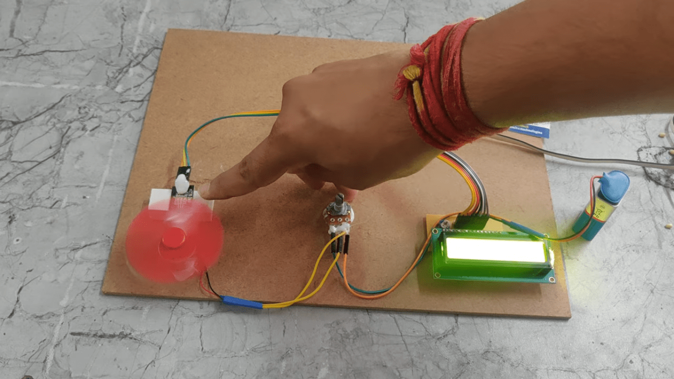
- Non contact tachometer using Hall Effect sensor.
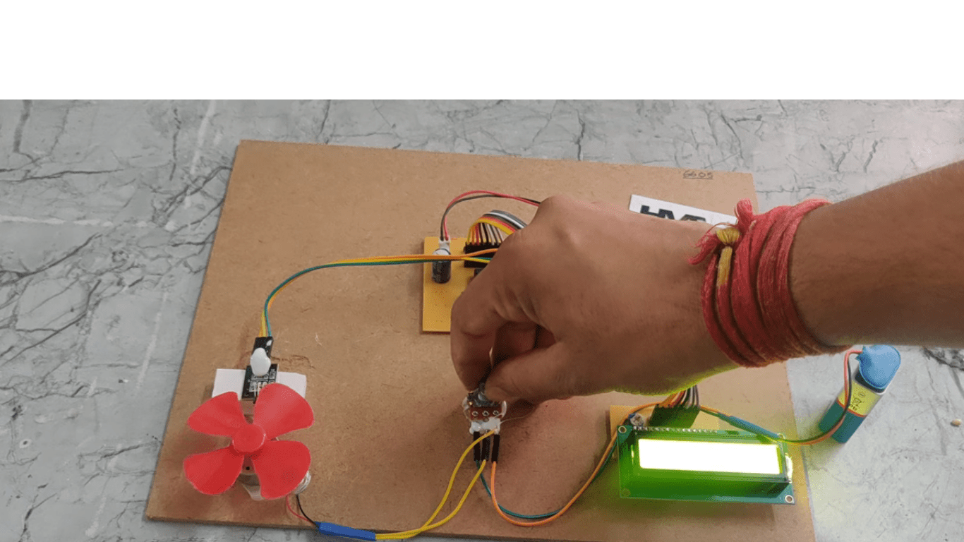
- DC motor speed change using potentiometer.
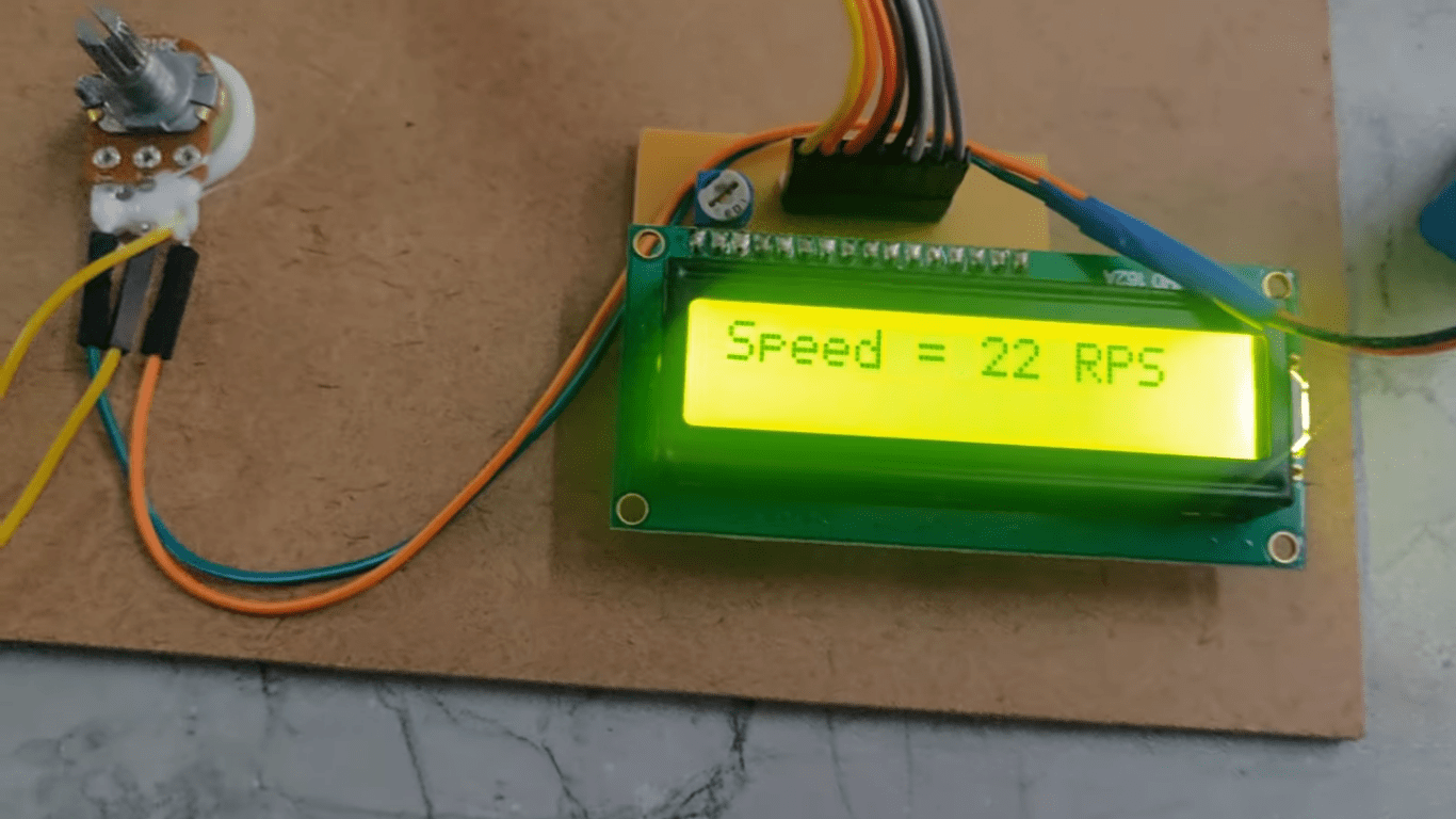
- Display of speed on LCD.
- Characteristics of Hall effect sensors.
- LCD interfacing with micro controller
- DC motor and Driver interfacings.
- Embedded C programming.
- PCB design.
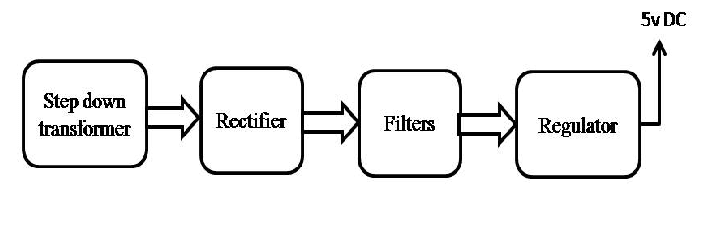
- Regulated power supply.
- Microcontroller.
- DC motor with driver.
- Potentiometer.
- Hall Effect Sensor.
- LED indicators.
- LCD Display with driver
- Crystal oscillator.
- Reset.
- LED indicators.
- PIC-C compiler for Embedded C programming.
- PIC kit 2 programmer for dumping code into Micro controller.
- Express SCH for Circuit design.
- Proteus for hardware simulation.