Subtotal ₹14,250.00


The purpose of this project is to construct a real time digital clock with battery back up protection for preserving the time settings. In this Project one digital clock is designed using a microcontroller and display on the LCD (Liquid Crystal Display).
While actually giving in to our body’s natural wants such as sleep, we are keeping the balance beam in an upright and neutral position, generally a good thing to do. But life comes and calls quite often, many times forcing us to put hunger, drowsiness, and other basic human needs on the backburner in order to seal the deal and get the job done.
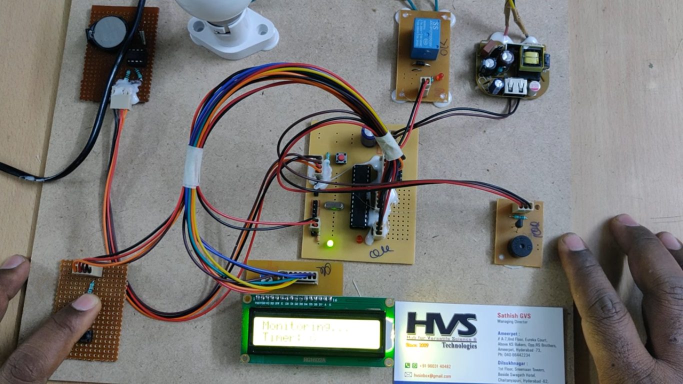
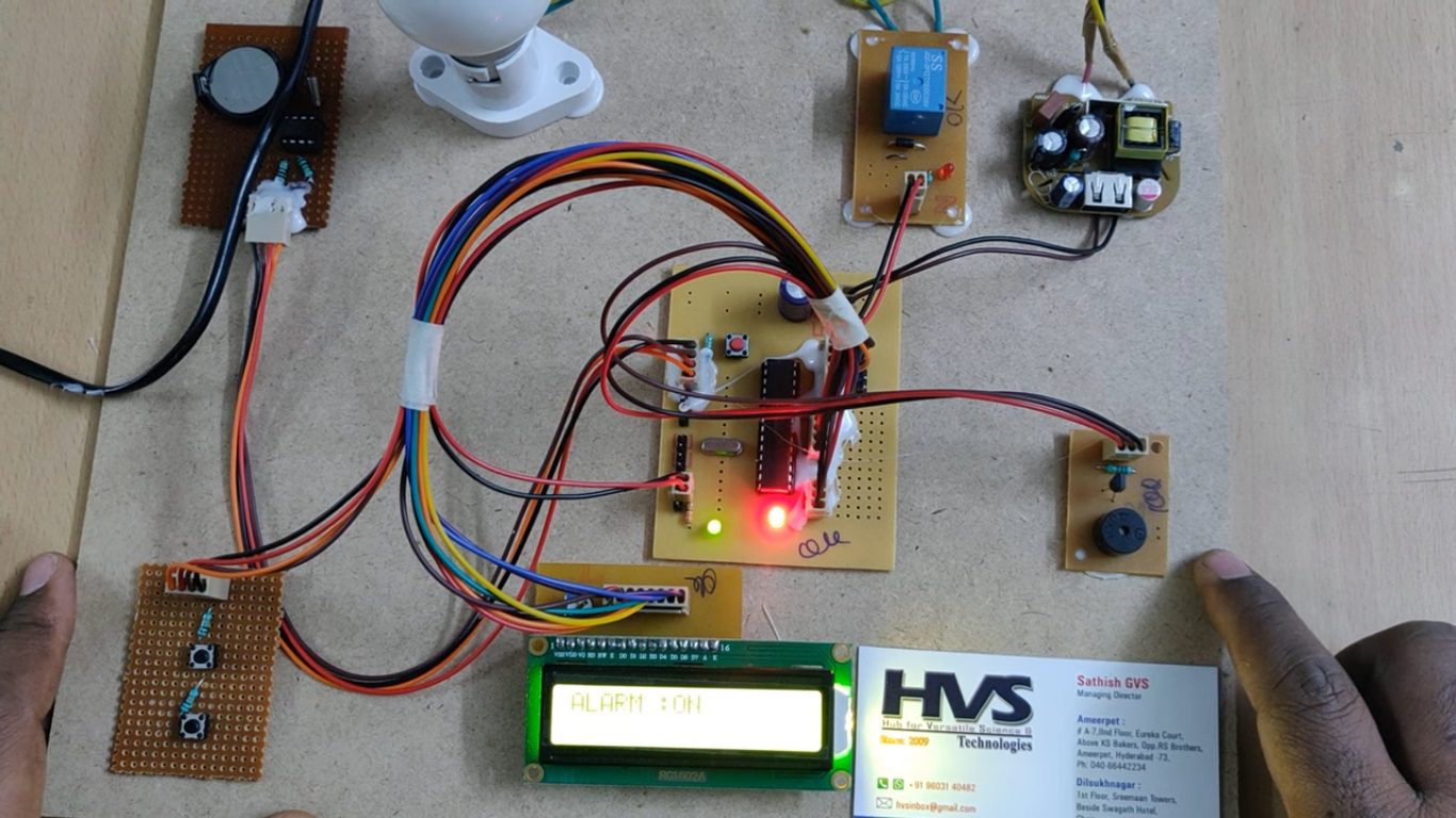
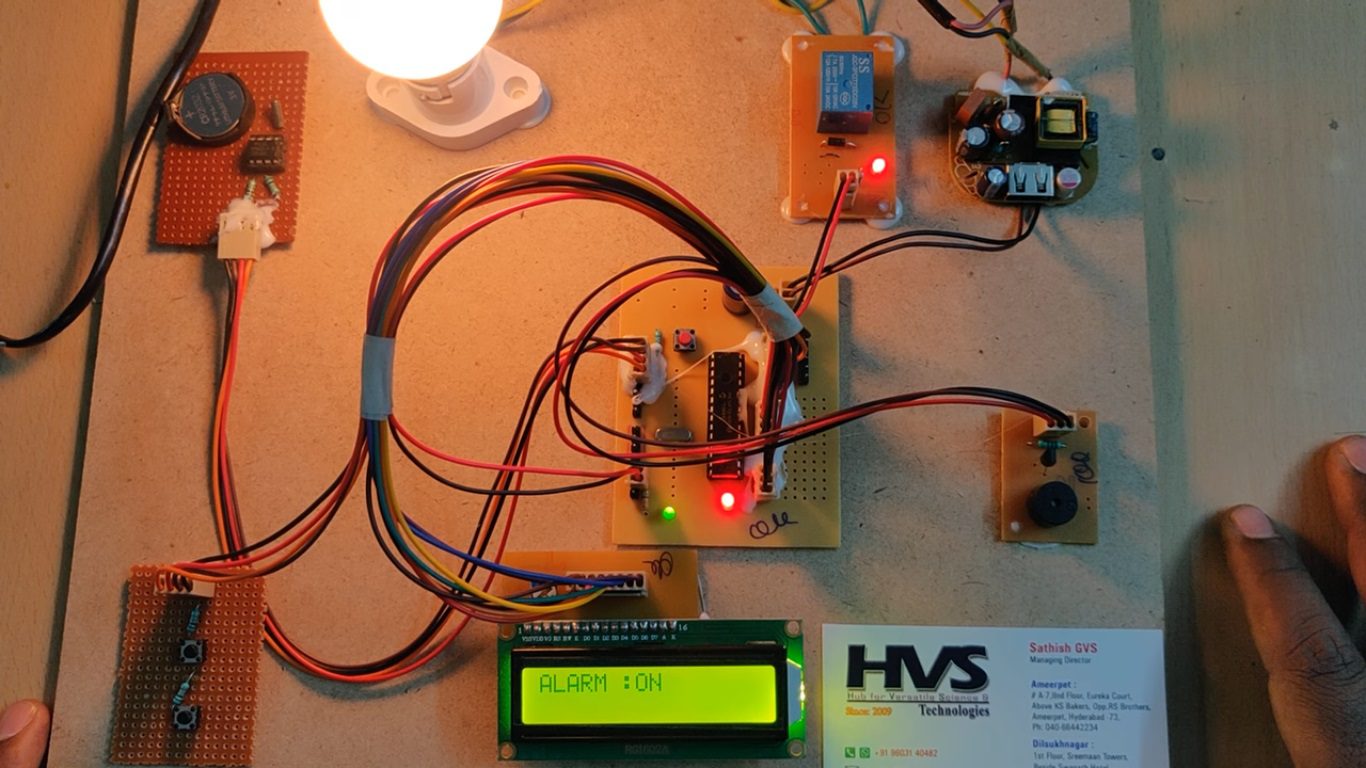
So here’s the scenario, this circuit saves both time and electricity for students. It helps to prevent them for dozing off while studying, by sounding a beep for few minutes. If timer is not reset during this time, it means the student is in deep sleep or not in the room, and the circuit switches off the light and fan in the room, thus preventing the wastage of electricity.
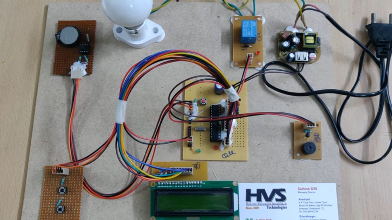
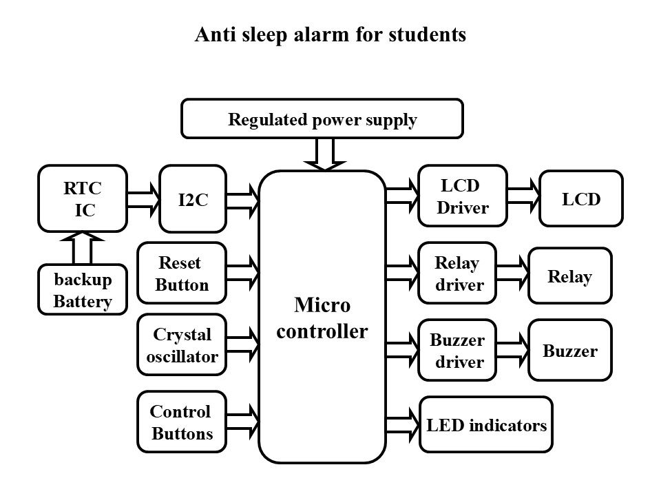
The microcontroller is the heart of the unit & controls all the blocks. One Real Time Clock (RTC) is interfaced with microcontroller through I2C bus. The RTC also has RAM, which is used to store the user data. The controller reads the real time from RTC and that is displayed in LCD display connected with microcontroller through driver. The system also has another feature, when the person receives the alarm for the specified time he need to reset it , if he fails to do the system alerts by switching OFF the electrical appliances like lights, fans etc using relay switches.
The firmware is developed in Embedded ‘C’ language and compiled using PIC ‘C’ compiler. The final output of compiler will be in the form of Hex file. That Hex file is programmed/copied in to PIC microcontroller Flash program memory.
The objectives of the project include:
 Block Diagram:
video:
Block Diagram:
video:
- Automatic controlling of electrical devices.
- Dynamic alarm setting options.
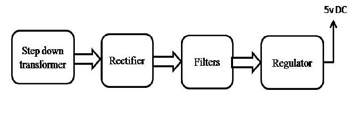
- Regulated Power Supply.
- PIC Microcontroller.
- Relay with driver.
- Real Time Clock (RTC).
- LCD with driver.
- LED Indicators.
- Buzzer with driver.
- Crystal
- PIC-C compiler for Embedded C programming.
- PIC kit 2 programmer for dumping code into Micro controller.
- Express SCH for Circuit design.
 Block Diagram:
 video: