No products in the cart.


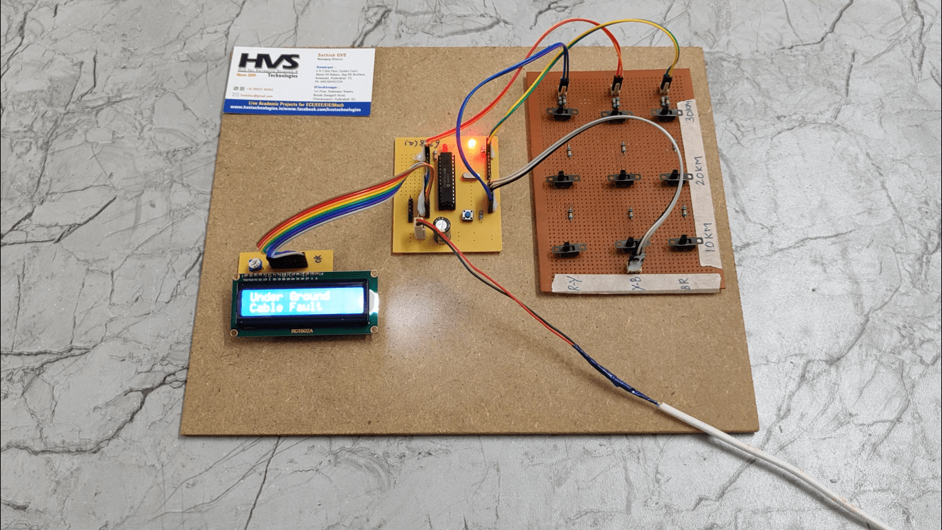
The objective of this project is to determine the distance of underground cable fault from base station in kilometres. The underground cable system is a common practice followed in many urban areas. While a fault occurs for some reason, at that time the repairing process related to that particular cable is difficult due to not knowing the exact location of the cable fault. The proposed system is to find the exact location of the fault.
The project uses the standard concept of Ohms law i.e., when a low DC voltage is applied at the feeder end through a series resistor (Cable lines), then current would vary depending upon the location of fault in the cable. In case there is a short circuit (Line to Ground), the voltage across series resistors changes accordingly, which is then fed to an ADC to develop precise digital data which the programmed microcontroller would display in kilometres.
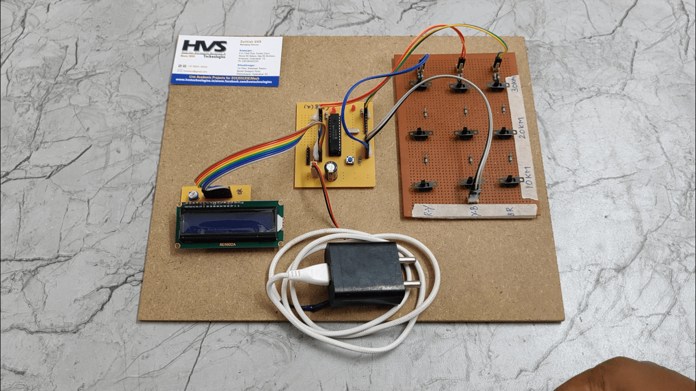
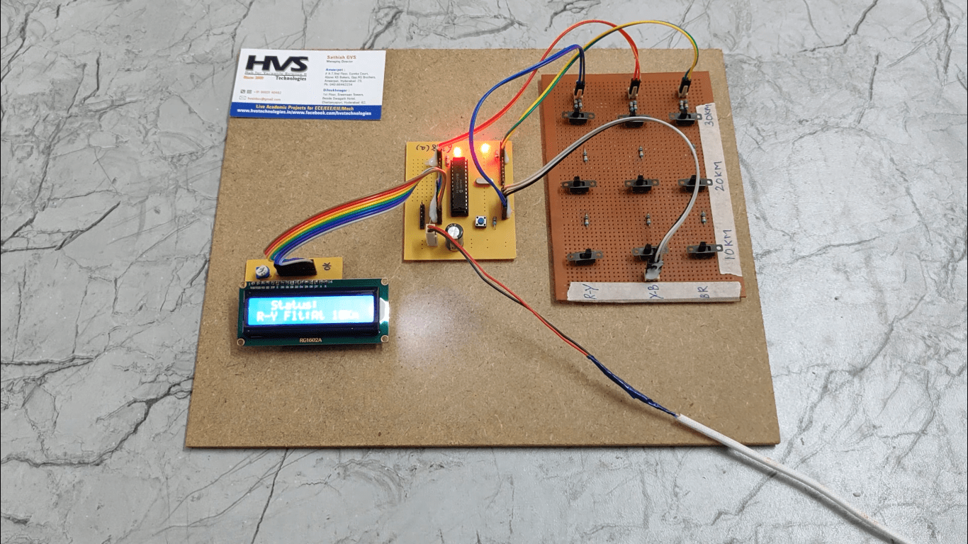
The project is assembled with a set of resistors representing cable length in KM’s and fault creation is made by a set of switches at every known KM to cross check the accuracy of the same. The fault occurring at a particular distance and the respective phase is displayed on a LCD interfaced to the microcontroller.
The main objectives of the project are:
 video:
- Fault detection in under ground cables
- Tracing of exact location where fault has occurred.
- Display continuously on LCD.
- Fault detection techniques
- Interfacing LCD and microcontroller.
- Conversion of AC supply to DC supply.
- Embedded C programming.
- PCB design concepts
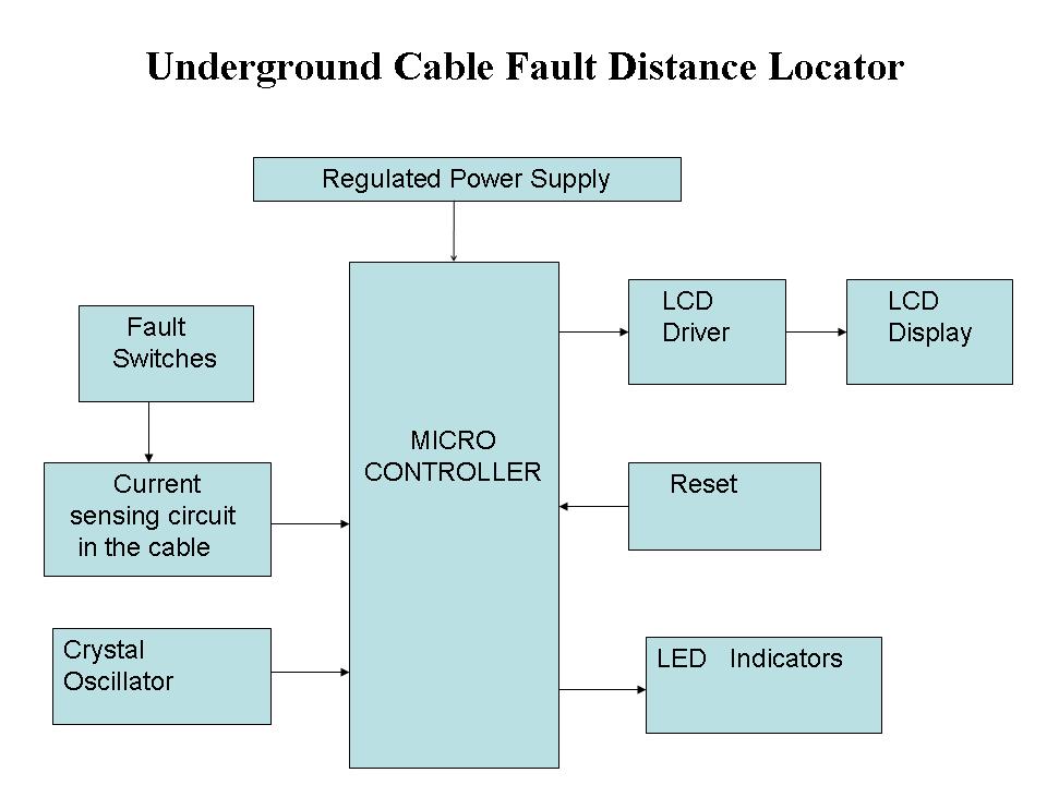
- Regulated power supply
- Microcontroller
- LED indicators.
- Fault switches
- Reset
- LCD with driver.
- Crystal
- PIC-C compiler for Embedded C programming.
- PIC kit 2 programmer for dumping code into Micro controller.
- Express SCH for Circuit design.
 video: