No products in the cart.


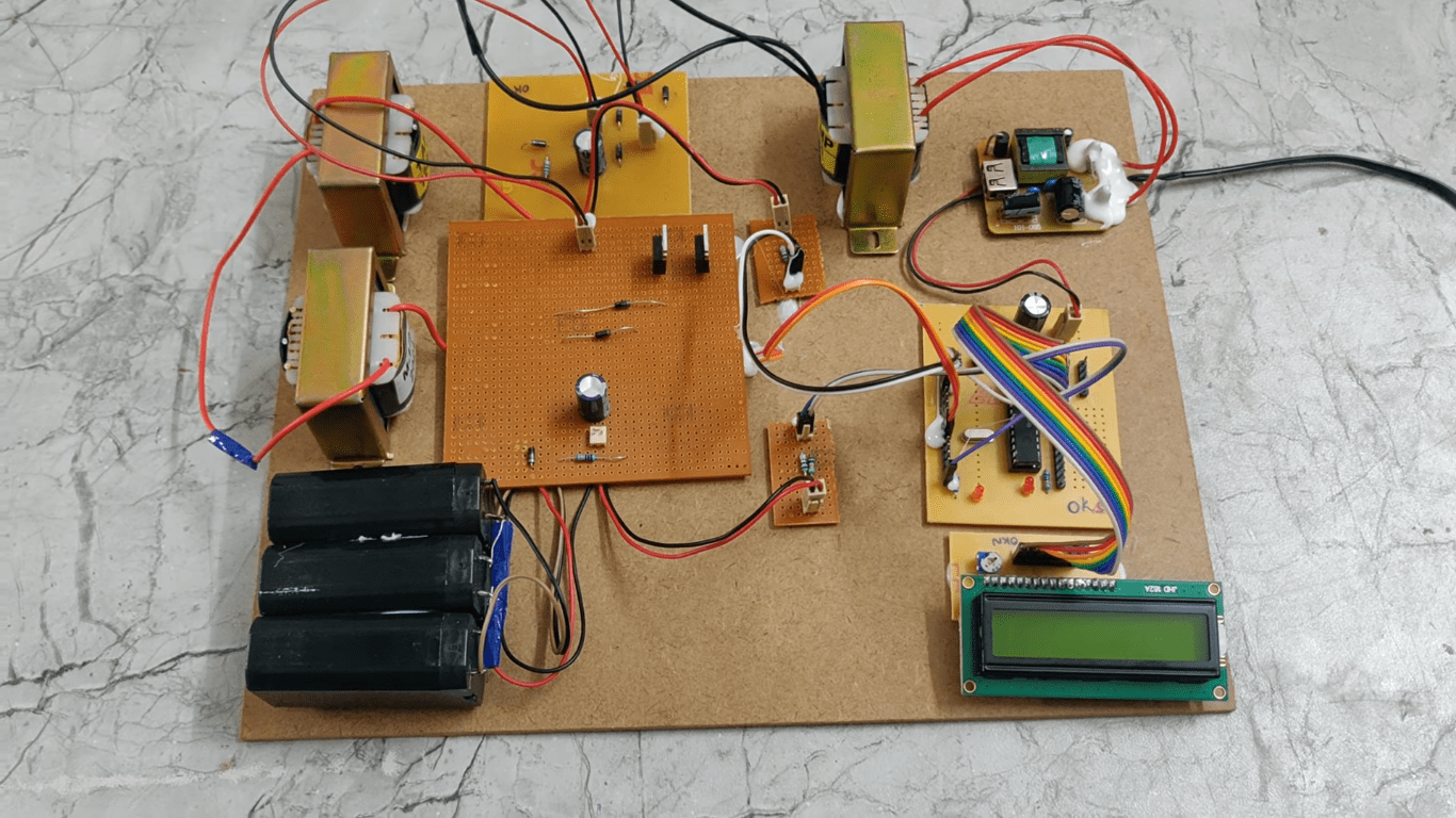
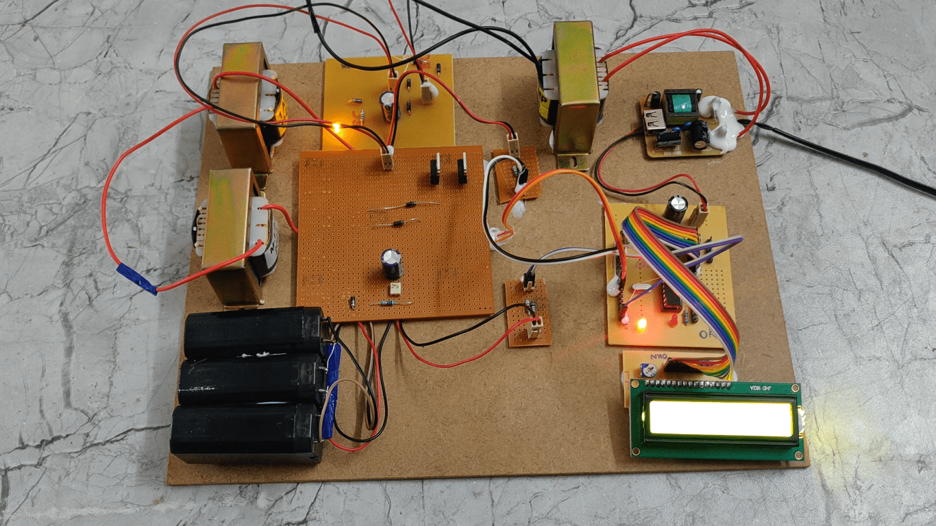
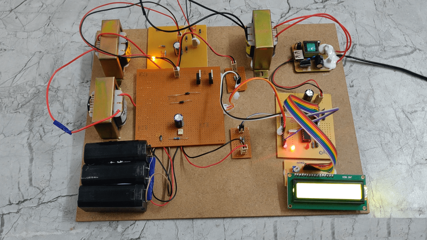
This project proposes the design and implementation of an interleaved buck-boost converter system for electric vehicle (EV) battery charging, utilizing a PIC microcontroller, voltage sensors, LCD display, and the interleaved buck-boost converter topology. The system aims to efficiently regulate the charging process of EV batteries by dynamically adjusting the output voltage based on battery parameters and charging requirements. The PIC microcontroller serves as the central control unit, coordinating the operation of the voltage sensors and controlling the interleaved buck-boost converter. Real-time battery status information is displayed on the LCD, providing users with feedback on the charging process. By employing the interleaved buck-boost converter topology, the system achieves high efficiency and reliability in converting the input voltage to the desired output for EV battery charging. Overall, this system offers a promising solution for enhancing the performance and reliability of EV battery charging systems in electric vehicles. Based on the input voltage microcontroller will generate the PWM signals to the mosfet which consist of interleaved buck-boost converter. Microcontroller will measure the input and output voltages of interleaved buck boost converter will be display on LCD. To achieve this task microcontroller loaded program written in embedded C language.
The main objectives of the project are:
 video:
- Design an interleaved buck-boost converter.
- Monitoring the input and output voltages of interleaved buck boost converter on LCD.
- To achieve this task using PIC microcontroller.
- Regulated power supply.
- PIC microcontroller.
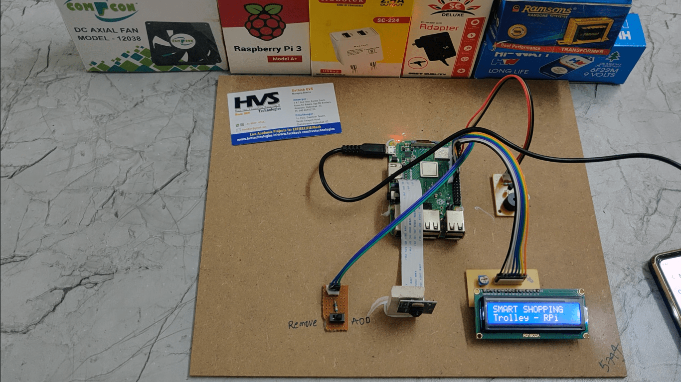
- LCD display.
- Voltage sensors.
- Transformers
- Inter leaved buck-boost convertor.
- Crystal oscillator.
- Reset Button.
- LED indicator.
- PIC-C compiler for Embedded C programming.
- PIC kit 2 programmer for dumping code into Micro controller.
 video: