No products in the cart.


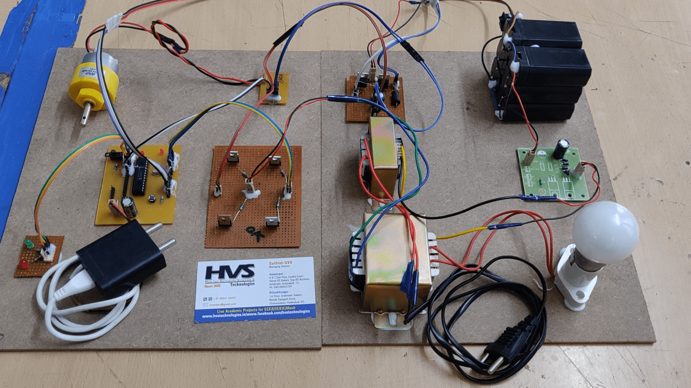
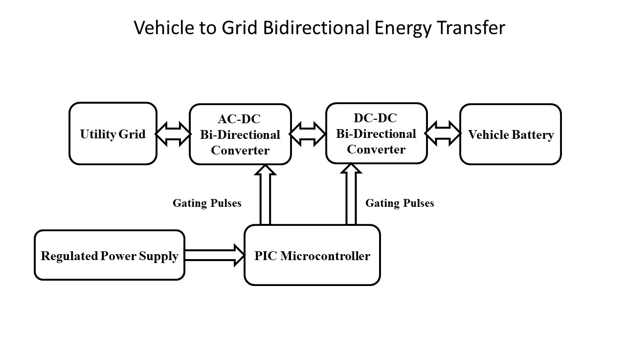
The primary objective of a project is to achieve a flow of power between power grid and electric vehicle in both the directions. The system consists mainly of two power converter blocks: one which is a bidirectional AC to DC converter and the other being a bidirectional DC to DC converter that share a common DC link. The full-bridge AC to DC bidirectional converter acts as a rectifier during the G2V operating mode and the same acts as inverter during the V2G mode. DC to DC bidirectional converter acts as step down converter while charging the battery and in the step-up mode during the discharge of the battery. There is also a PIC Microcontroller to give the gating pulses to the converters used in this project.
Modes of Operation There are two basic modes of operation: Grid-to Vehicle(G2V) mode and Vehicle-to-Grid (V2G) mode
Grid-to Vehicle(G2V) mode:
In this mode of operation, the vehicle battery is charged from grid. Grid’s AC voltage is rectified to DC by an AC to DC converter operating in the rectifier mode. The output of this converter is fed to the DC link. The DC-to-DC converter operates in buck mode by stepping down the DC link voltage to the required battery charging voltage.Vehicle-to-Grid Mode of Operation:
In this operating mode, energy stored in the battery is fed back to the grid. The DC voltage from the battery is stepped up using the DC-DC converter operating in boost mode and is then converted to AC using the AC-DC converter operating in the inverter mode and is fed to grid. To feed the power back to grid, output of inverter should be synchronized with that of the grid. Here the proposed grid synchronization technique is using a hysteresis current control.
The major features of this project are:
- Achieve flow of power between power grid and the electric vehicle in both the directions
- Use of Bi directional AC-DC Converter that acts as rectifier and inverter alternatively in two modes respectively
- Use of Bi Directional DC-DC Converter that acts as step down converter and step up converter alternatively in two modes respectively.
- Utility Grid
- AC-DC Bidirectional Converter
- DC-DC Bidirectional Converter
- Vehicle Battery
- PIC Microcontroller
- Regulated Power Supply
- PIC C compiler software for embedded C programming.
- PIC Kit 2 software programmers for dumping code into PIC Microcontroller.
- Express SCH for Circuit design.