Subtotal ₹11,250.00


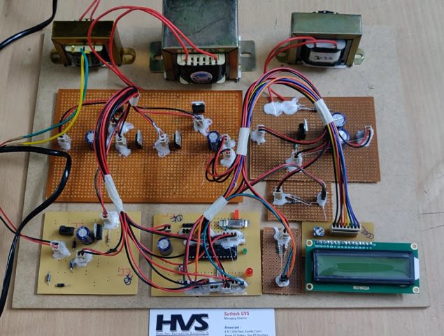
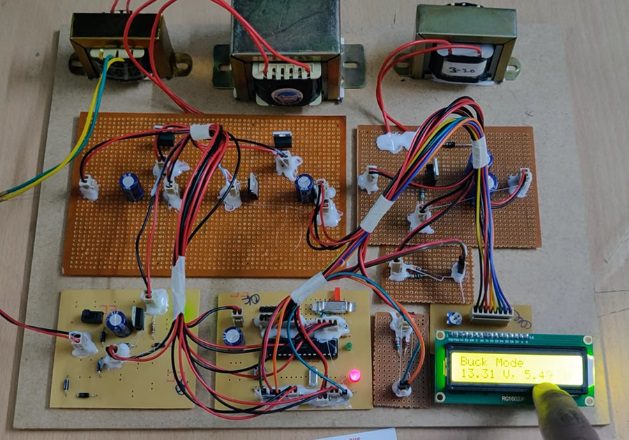
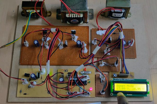
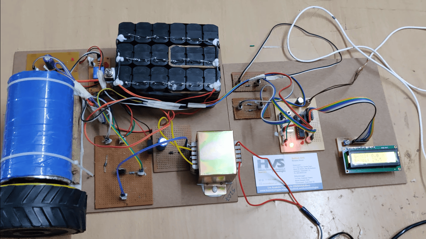
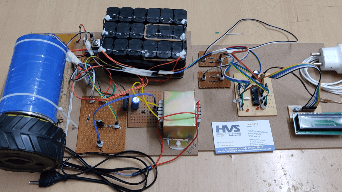
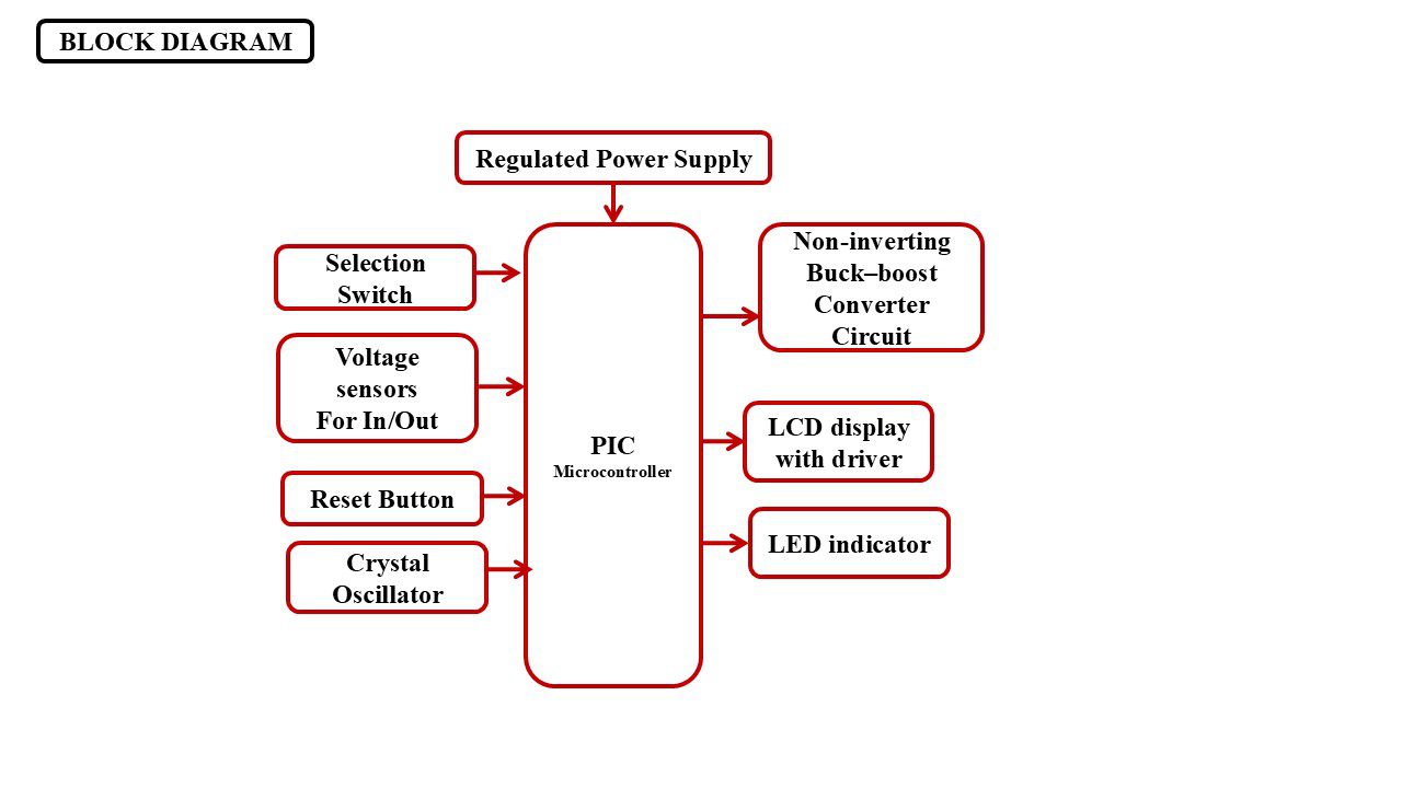
The increasing demand for efficient DC–DC power conversion in renewable energy systems, electric vehicles, battery-operated devices, and portable electronic applications has created the need for converters capable of operating over a wide range of input voltages. A buck–boost converter is widely used because it can perform both step-down and step-up voltage conversion. However, conventional buck–boost converters may experience an operational dead zone and output voltage fluctuations during the transition between buck and boost operating modes, especially when the input voltage is close to the desired output voltage. This project presents a Multimode Smooth Switching Strategy for Eliminating the Operational Dead Zone in a Buck–Boost Converter using a PIC microcontroller-based control system. The proposed system consists of a PIC microcontroller, non-inverting buck–boost converter circuit, input and output voltage sensors, selection switch, PWM control circuit and an LCD display. The voltage sensors continuously measure the input and output voltages and send the corresponding signals to the PIC microcontroller. The selection switches allow the user to select different operating modes of the converter. Based on the measured voltage conditions and selected operating mode, the PIC controller automatically determines the appropriate operation, such as buck mode, boost mode, or smooth transition mode, and generates suitable PWM signals for efficient converter control. The LCD display provides real-time monitoring of input voltage, output voltage, selected operating mode, and system status. The proposed smooth switching strategy reduces voltage fluctuations, minimizes switching losses, improves output voltage regulation, and eliminates the operational dead zone during mode transitions. The system provides improved efficiency, reliability, and dynamic performance, making it suitable for solar energy systems, battery-powered applications, electric vehicles, and other renewable energy and power electronic applications.
Objectives:
 video:
- To design a PIC microcontroller-based multimode buck–boost converter.
- To measure the input and output voltages using voltage sensors.
- To achieve smooth switching between buck and boost operating modes.
- To eliminate the operational dead zone and maintain a stable output voltage.
- To display the voltage values and operating mode on an LCD.
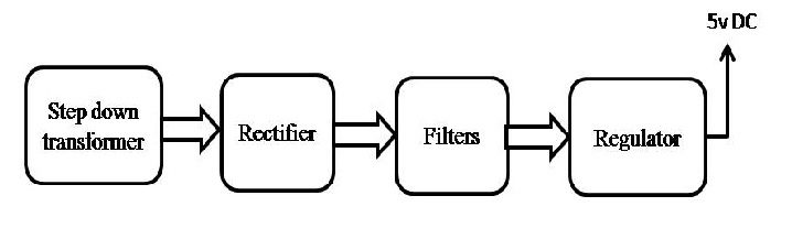
- Regulated Power Supply.
- PIC MICROCONTROLLER.
- PWM signals.
- Non-inverting buck-boost converter.
- Voltage sensors.
- LCD display.
- Crystal oscillator.
- Reset button.
- LED indicator.
- PIC-C compiler for Embedded C programming.
- PIC kit 2 programmer for dumping code into Micro controller.
- Express SCH for Circuit design.
 video: