No products in the cart.


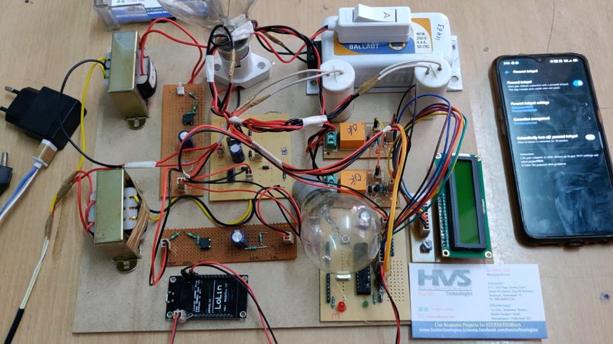
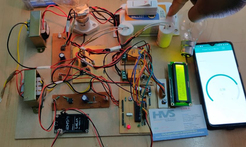
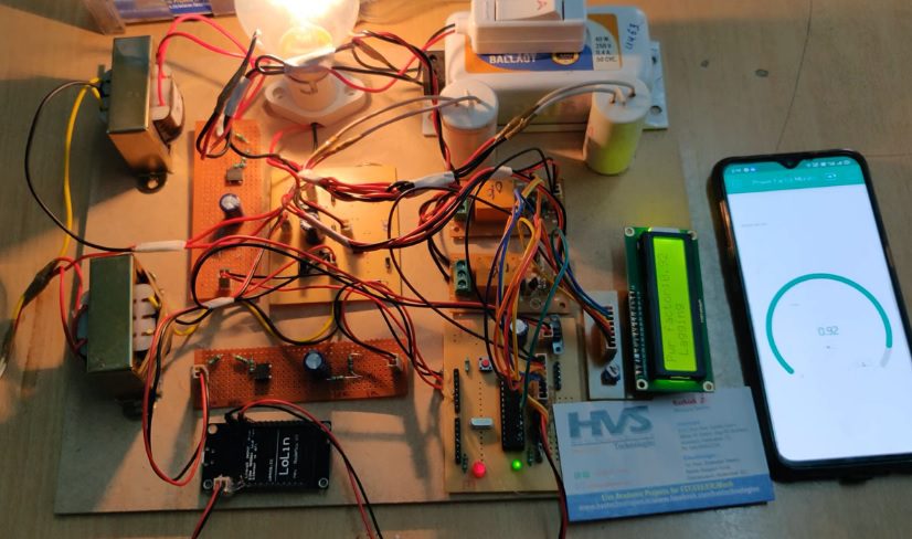
This project includes a new implementation method to improve power factor for both leading and lagging loads using PIC Microcontroller after determining their zero crossing locations of voltage and current waveforms by zero cross detectors (ZCD). Capacitive and inductive banks are used for the compensation of power factor according to nature of load which is determined based on microcontroller algorithm.
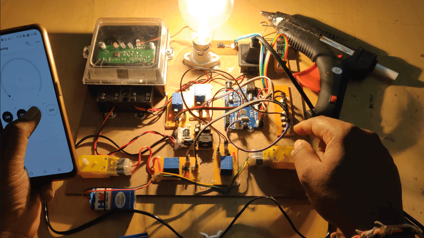
To design this project microcontroller plays a major role. The interfaced devices to the microcontroller are nodemcu, Zero cross detector, Potentiometer, Current Transformer, Voltage Transformer, Capacitive Bank and Inductive Bank. The main purpose is to detect the zero crossing of the voltage and current and then switching of capacitive and inductive banks based on microcontroller algorithm.
The voltage is first stepped down using potential transformers and the current is stepped down using current transformer whose rating is decided based on maximum rating of your load. These two waves of voltage and current are passed through zero cross detectors (ZCD). The waves that appear across the output of the ZCD are the square waves and their amplitude approaches almost to the biasing of the operational amplifier. These two waves are then fed to microcontroller so that it can measure the phase delay between the voltage and current waveforms and then show the power factor accordingly based on the proposed algorithm. The microcontroller then based on number of counts decides the power factor and displays it on LCD. The system can be programmed using Embedded ‘C’ language.
Major blocks present in this project:
 Block Diagram:
video:
Block Diagram:
video:
- Regulated power supply
- Micro controller
- Potentiometer
- Voltage Transformer
- Current Transformer
- Capacitive Bank
- Inductive Bank
- Node MCU.
- Arduino IDE for Programming
- Express SCH for Circuit design
- Blynk APP.
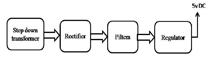 Block Diagram:
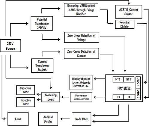 video: