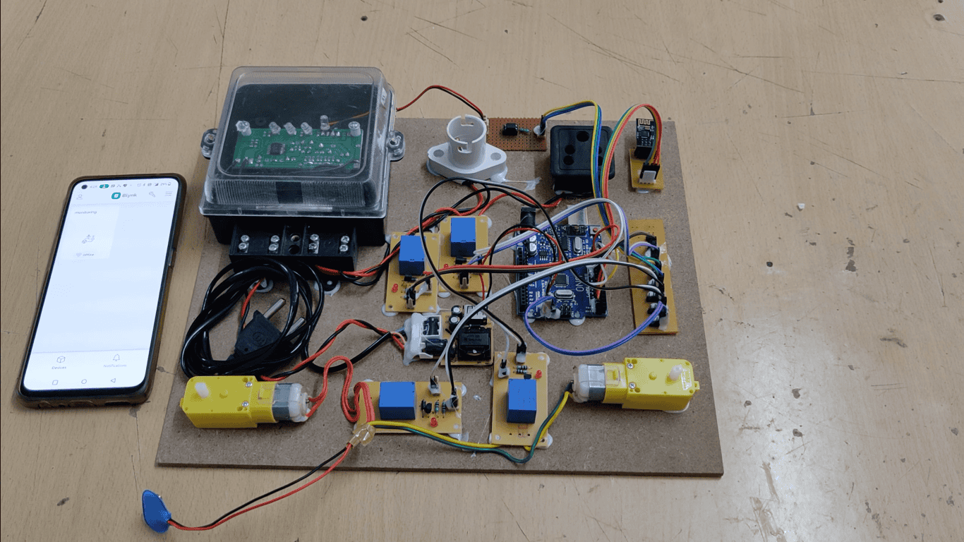
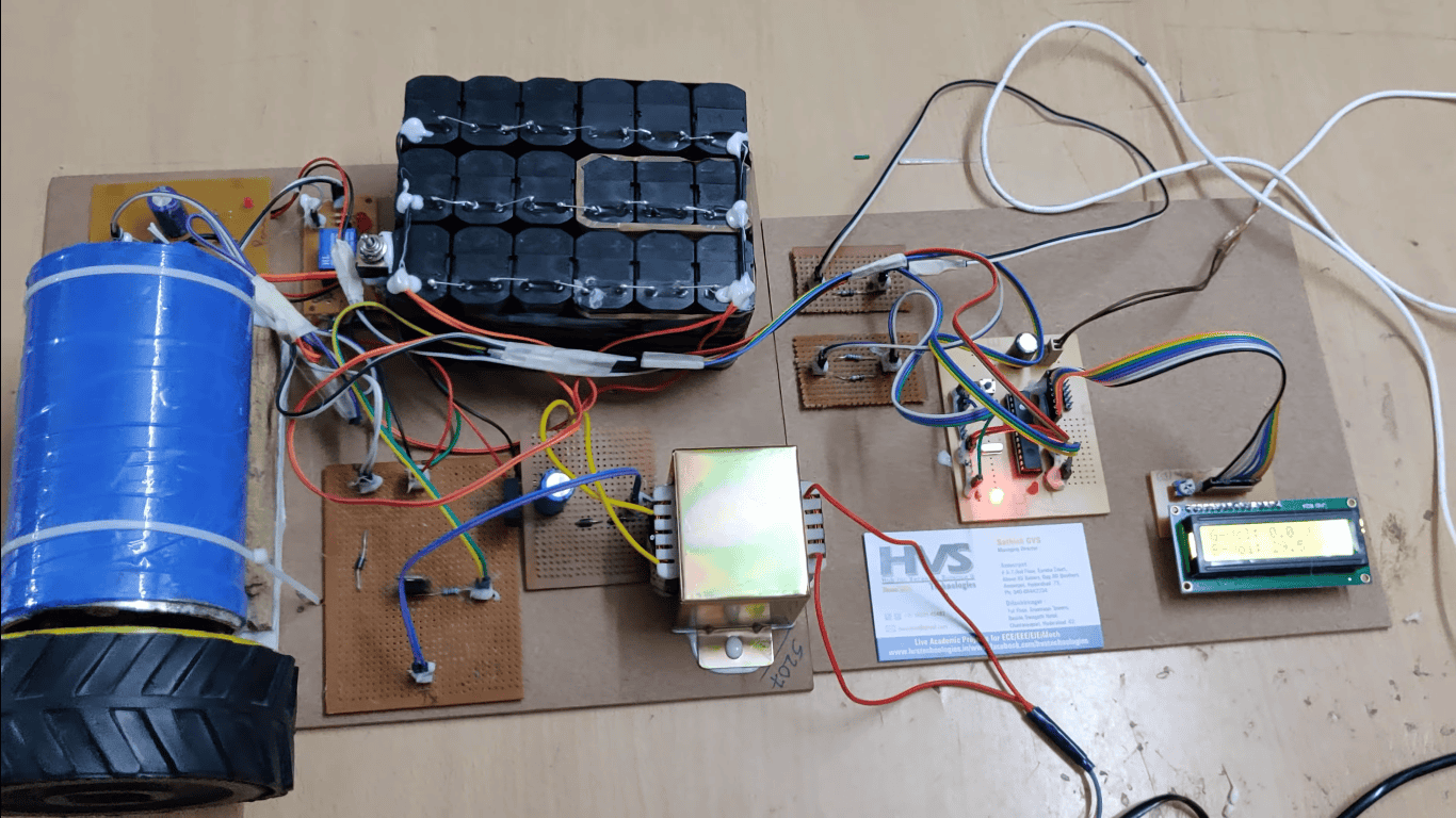
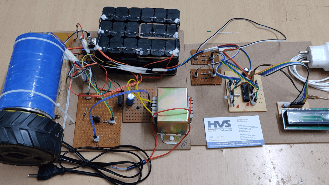
HVS-2701. A High Efficiency Non-Isolated Buck-Boost Converter Based on ZETA Converter.
₹9,500.00
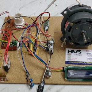
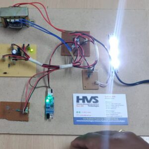
The main aim of the project is to design a new transformer less buck- boost converter based on ZETA converter. Fuel cell and photovoltaic cell are the two most vital energies.
The main aim of the project is to design a new transformer less buck- boost converter based on ZETA converter. Fuel cell and photovoltaic cell are the two most vital energies. However, the voltage levels of these sources are too low and unpredictable unstable, varying with climate conditions such as solar irradiance and temperature. Therefore, high voltage gain converters are required for photovoltaic cell and fuel cell systems.
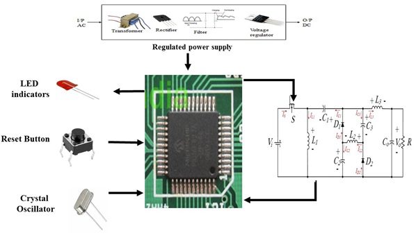
To design this project the buck-boost convertor interfaced to Microcontroller. The proposed converter has the ZETA converter advantages such as, buck-boost capability, input to output DC insulation and continuous output current. The suggested converter voltage gain is higher than the classic ZETA converter. In the presented converter, only one main switch is utilized. The proposed converter offers low voltage stress of the switch; therefore, the low on- state resistance of the main switch can be selected to decrease losses of the switch. The presented converter topology is simple; hence, the control of the converter is simple. The converter has the continuous output current.
Objectives:
To design a transformer less ZETA-based Buck-Boost converter.
To increase the low input voltage from solar and fuel cell sources.
To provide both step-up and step-down voltage conversion.
To achieve high voltage, gain with low power losses.
To reduce the voltage stress on the switch.
To provide a continuous output current.
To control the converter using a microcontroller.
To improve the efficiency and reliability of the converter.
 1 × ₹4,500.00
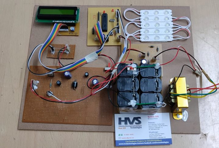
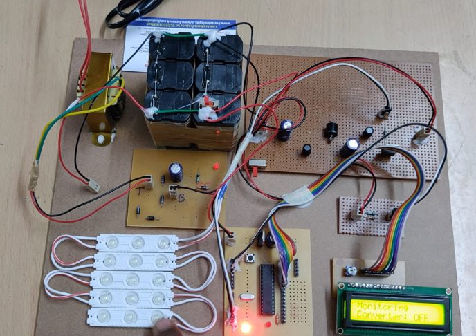
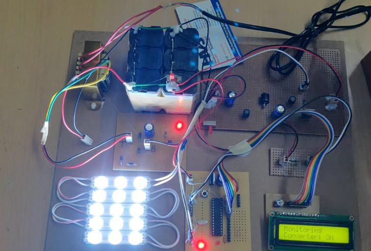
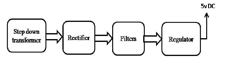 Block Diagram :
 video: