No products in the cart.


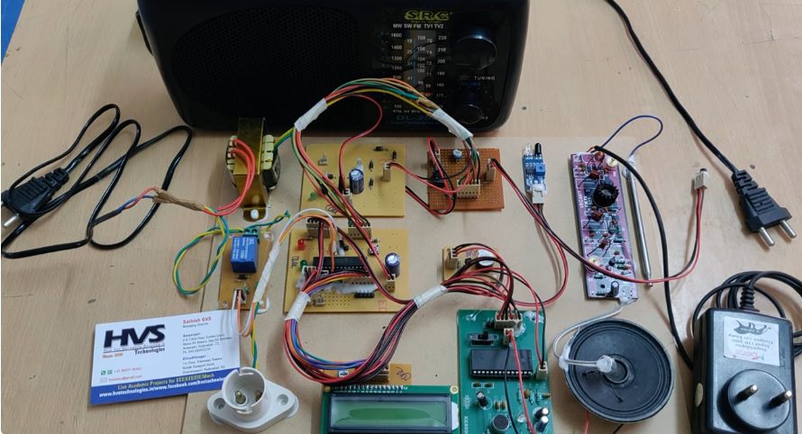
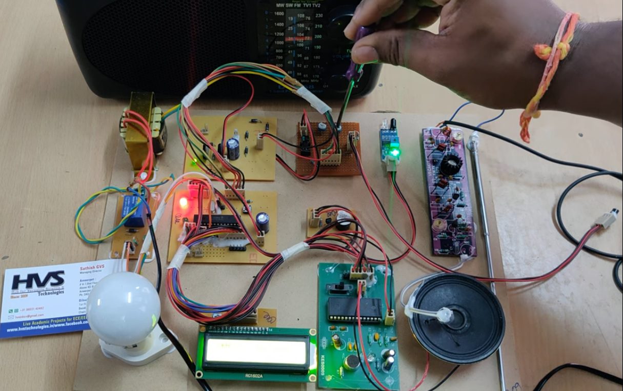
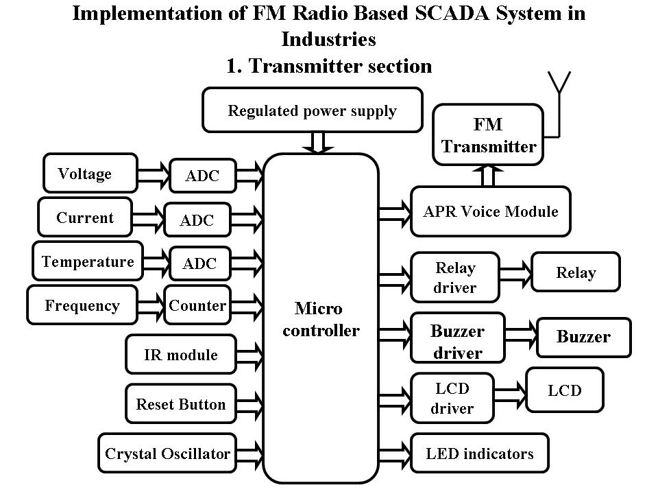
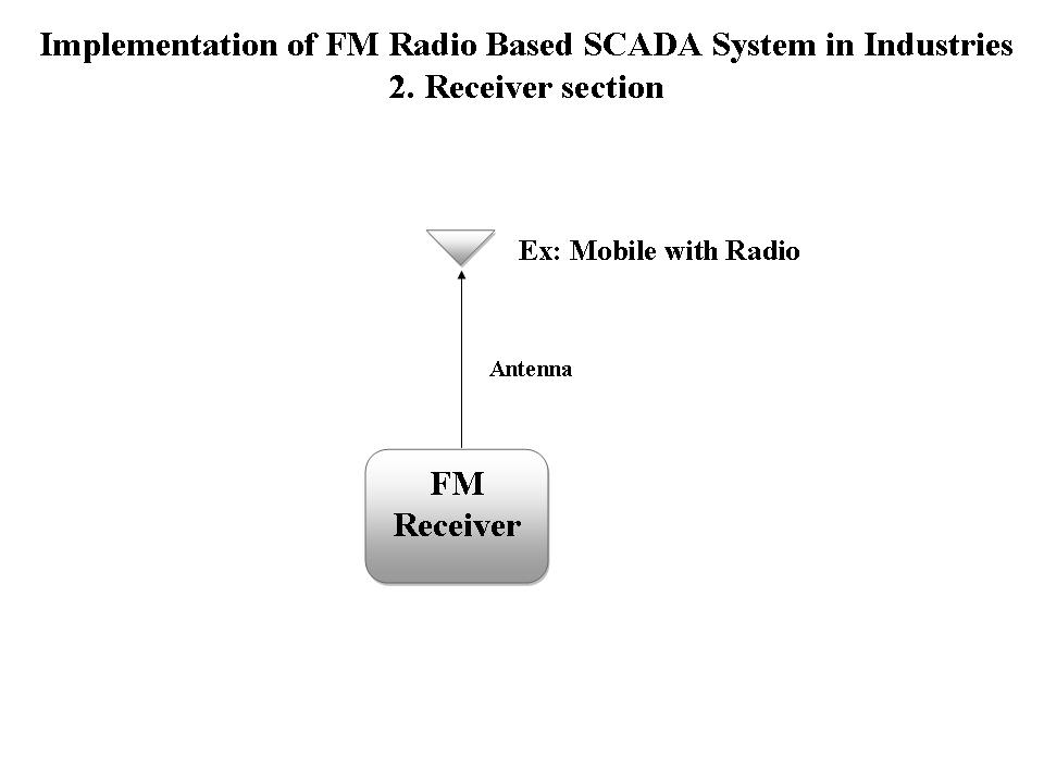
The purpose of this project is to acquire the remote electrical parameters like Voltage, Current and Frequency along with temperature and when these parameters exceeds beyond threshold limit then the system sends an alerting voice message using FM transmitter to the mobile phone at power station. If any unauthorized person crosses the fencing limits then the IR sensor will alert using FM announcements through mobile phone’s radio. This project is also designed to protect the electrical circuitry by operating an Electromagnetic Relay. This Relay gets activated whenever the electrical parameters exceed the predefined values. The Relay can be used to operate a Circuit Breaker to switch off the main electrical supply.
FM radio stations operate on frequencies between 88 and 108 MHz. The variable capacitor and your self-made inductor constitute a parallel LC circuit. It is also called a tank circuit and will vibrate at a resonant frequency which will be picked up your pocket FM radio. The transmitting range is dependent upon a number of variables. It uses Single wire or dipole antenna with supply voltage. The transmitter is constructed on a single-sided printed circuit board (PCB) with a silk screen overlay on top to aid in component placement. This FM Transmitter has an RF stage in its output to amplify the modulated signal.
This project makes use of an onboard computer which is commonly termed as microcontroller. This onboard computer can efficiently communicate with the different sensors being used. The controller is provided with some internal memory to hold the code. This memory is used to dump some set of assembly instructions into the controller. And the functioning of the controller is dependent on these assembly instructions. The controller is programmed using Embedded C language.
The objectives of the project include:
 Block Diagram:
video:
Block Diagram:
video:
- Sensing different electrical parameters (voltage, current, temperature).
- Alerting the people using Fm radio signals
- Visual and audible alerts using LCD and FM
- Producing buzzer alerts (if necessary).
- Automatic circuit breaking operation.
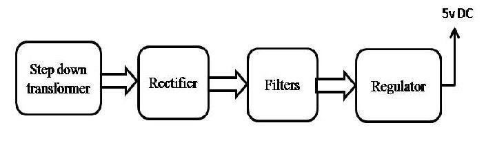
- Regulated Power Supply.
- PIC Microcontroller.
- LCD display with driver.
- Electromagnetic Relay with driver.
- Temperature Sensor.
- Voltage Sensor.
- Current Sensor.
- FM transmitter
- Voice module
- Buzzer with driver.
- Crystal
- IR Sensors.
- LED indicators.
- PIC-C compiler for Embedded C programming.
- PIC kit 2 programmer for dumping code into Micro controller.
- Express SCH for Circuit design.
 Block Diagram:
 video: