No products in the cart.


This project presents the design and implementation of a boost converter for a photovoltaic (PV) integrated standalone power system capable of producing a regulated high-voltage DC output. In many renewable energy applications, especially standalone systems, the available input voltage is often insufficient for direct utilization by high-voltage DC loads. Therefore, an efficient voltage boosting mechanism becomes essential.
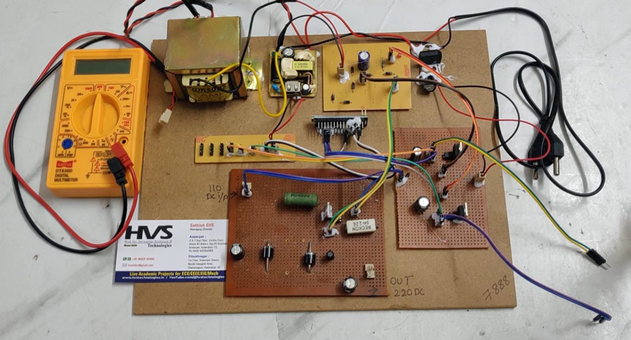
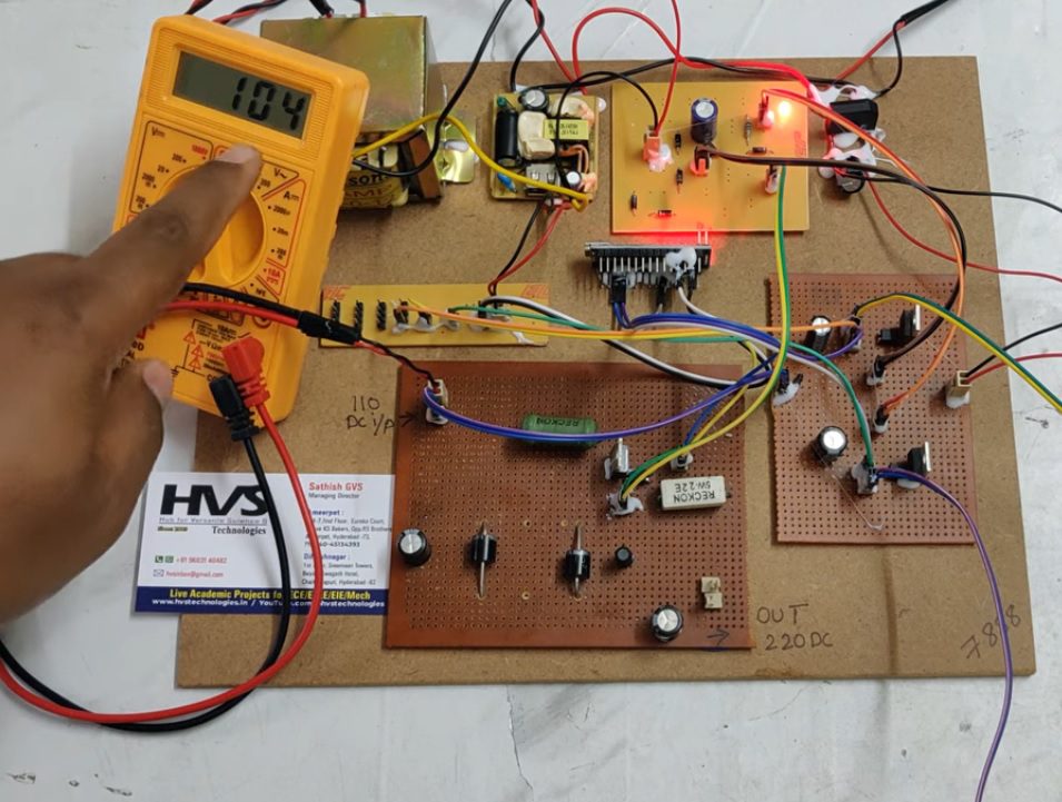
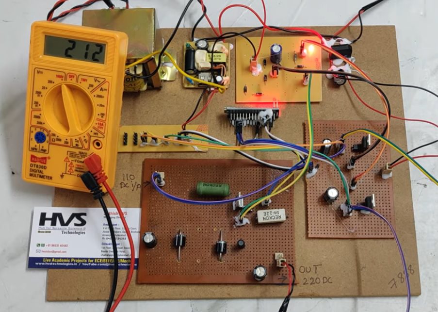
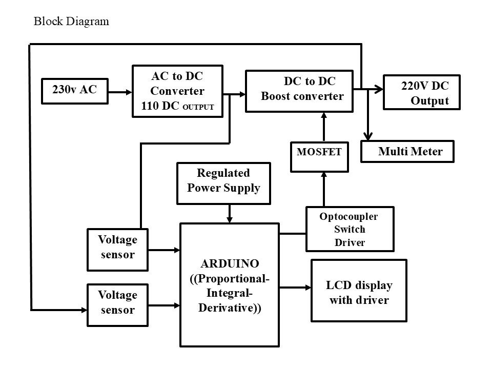
In the proposed system, a 230V AC input is first converted into a 110V DC supply using an AC to DC converter. This DC voltage is then fed into a DC-DC boost converter, which steps up the voltage to a higher level of approximately 220V DC suitable for standalone applications.
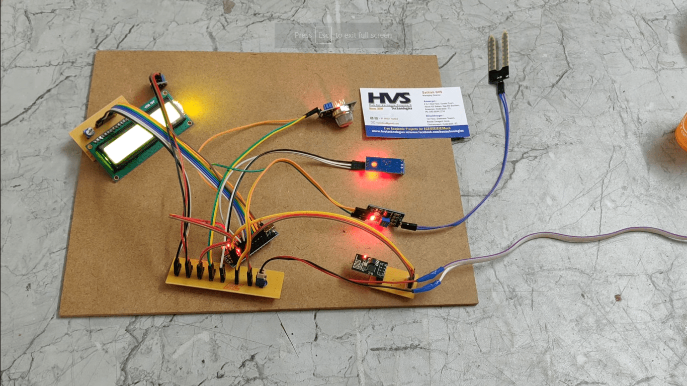
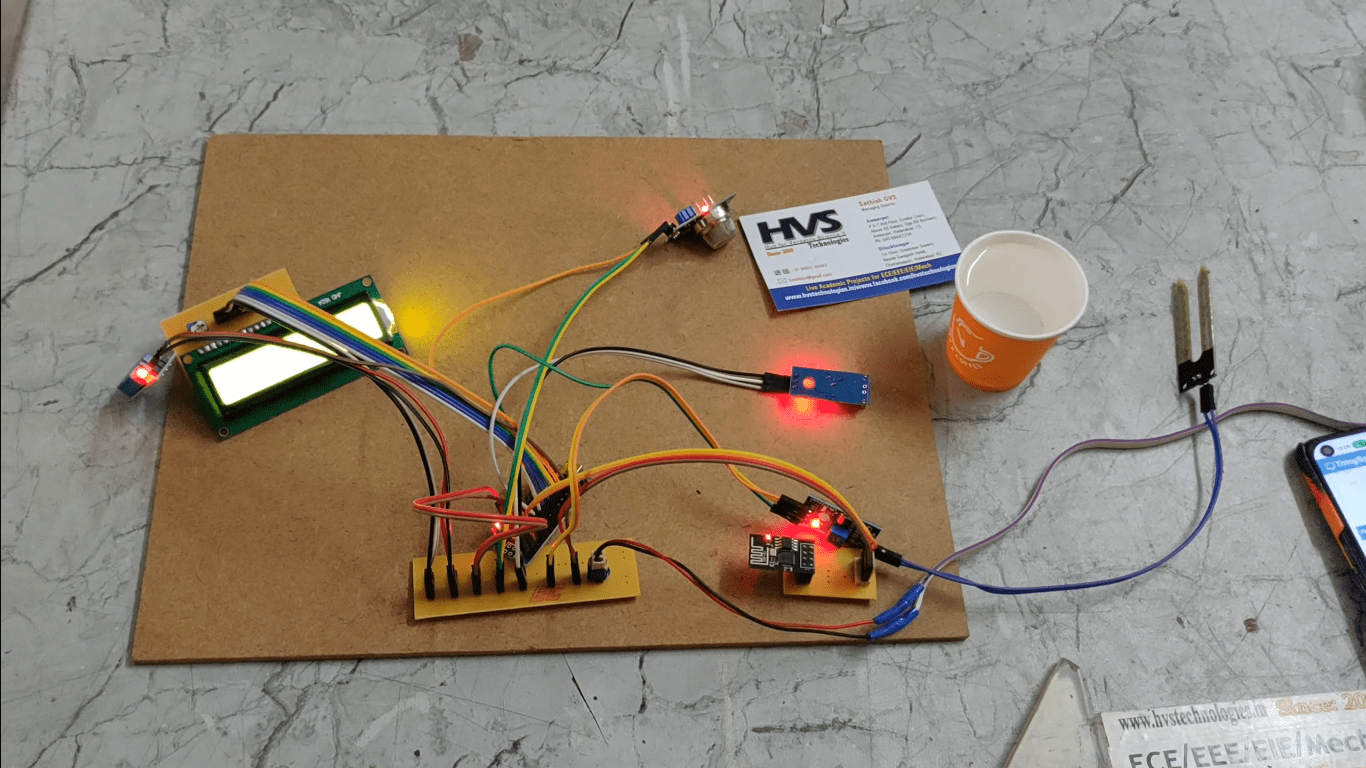
An Arduino-based Proportional-Integral-Derivative (PID) controller is used to regulate the output voltage of the boost converter. Voltage sensors are employed at both input and output stages to continuously monitor system performance and provide feedback to the controller. Based on this feedback, the Arduino generates PWM control signals to drive the MOSFET switch through an optocoupler-based switch driver circuit. The optocoupler ensures electrical isolation between the low-power control circuit and the high-power converter stage, enhancing system safety and reliability.
A regulated power supply is used to power the control circuitry, while an LCD display provides real-time monitoring of system parameters. A multimeter is integrated at the output stage for performance verification.
The proposed system ensures efficient voltage boosting, stable output regulation, and improved reliability, making it suitable for standalone renewable energy applications such as solar-based power systems, remote installations, and DC distribution networks.
The main Objectives of this project are:
 video:
• To convert 230V AC into usable DC voltage
• To design a DC-DC boost converter for voltage step-up
• To regulate output voltage using PID control
• To monitor input and output voltage using sensors
• To provide electrical isolation using optocoupler switching
• To control MOSFET switching using Arduino
• To display real-time voltage values on LCD
• To obtain stable 220V DC output.
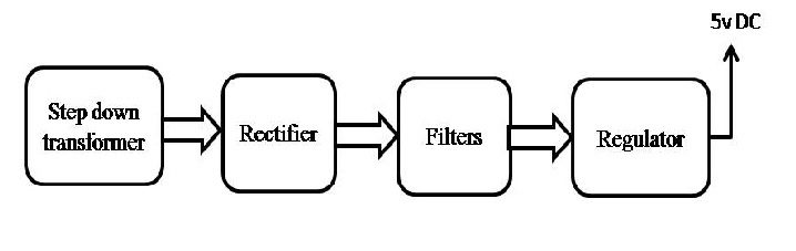
The major building blocks of this project are:- Regulated Power Supply.
- Arduino UNO.
- Two Voltage sensors.
- LCD display.
- AC to DC Converter.
- DC to DC converter.
- Mosfet.
- Optocoupler.
- Arduino IDE for compiling and dumping code into Microcontroller
- Express SCH for Circuit design.
 video: