No products in the cart.


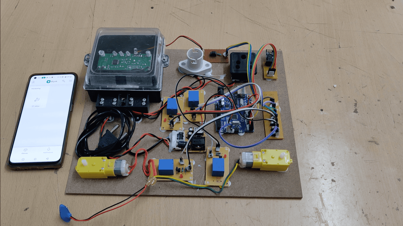
The purpose of this project is to monitor Power grid devices (Analog and Digital) remotely using smart phone. The Bluetooth modem provides the communication mechanism between the user and the microcontroller system by means of text messages.
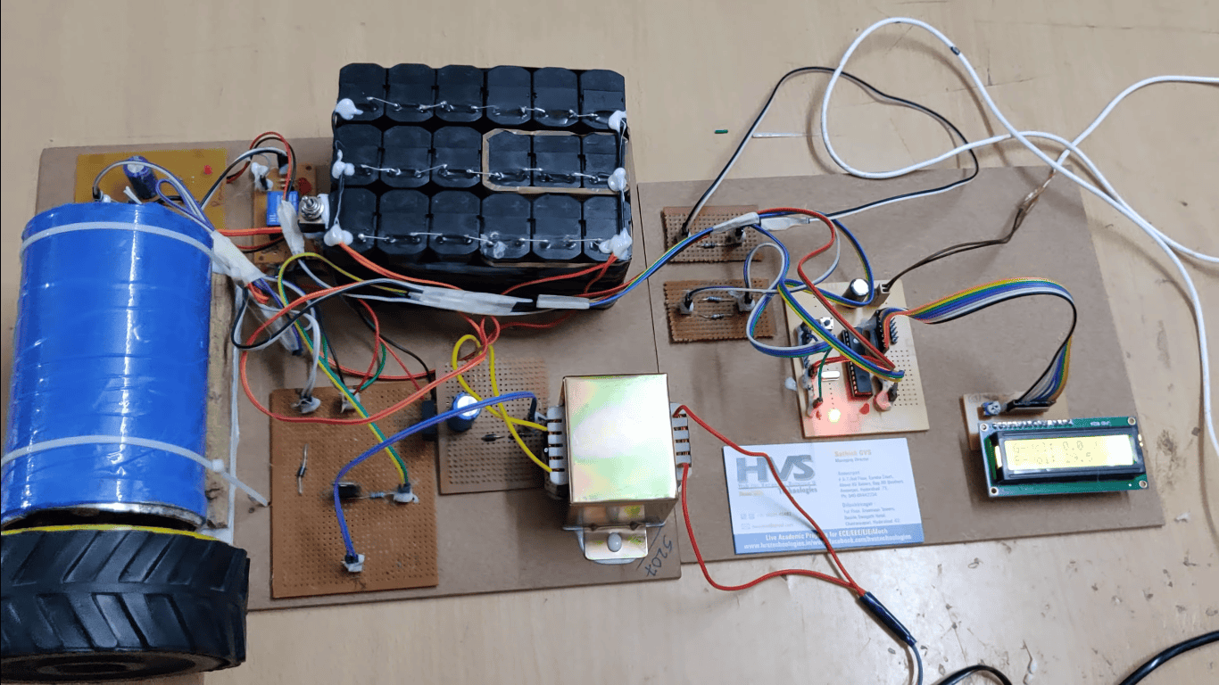
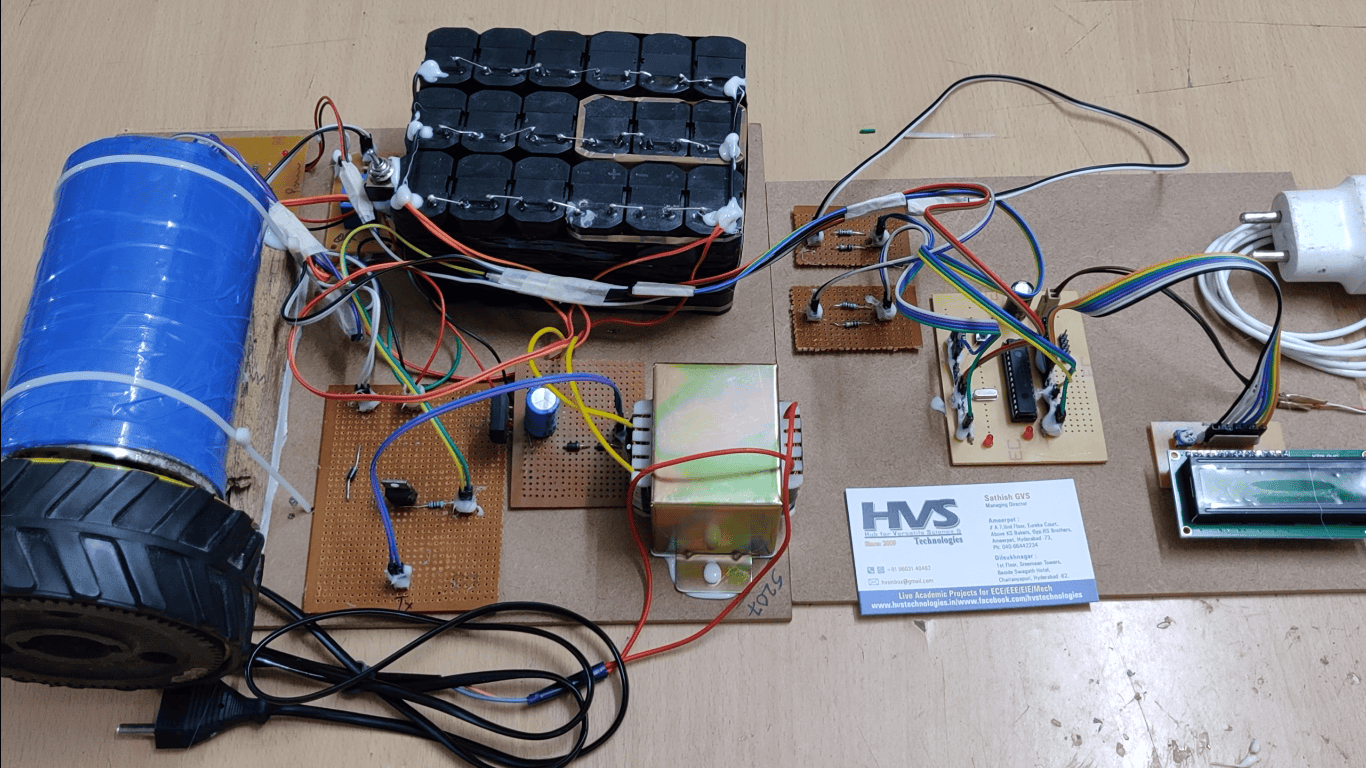
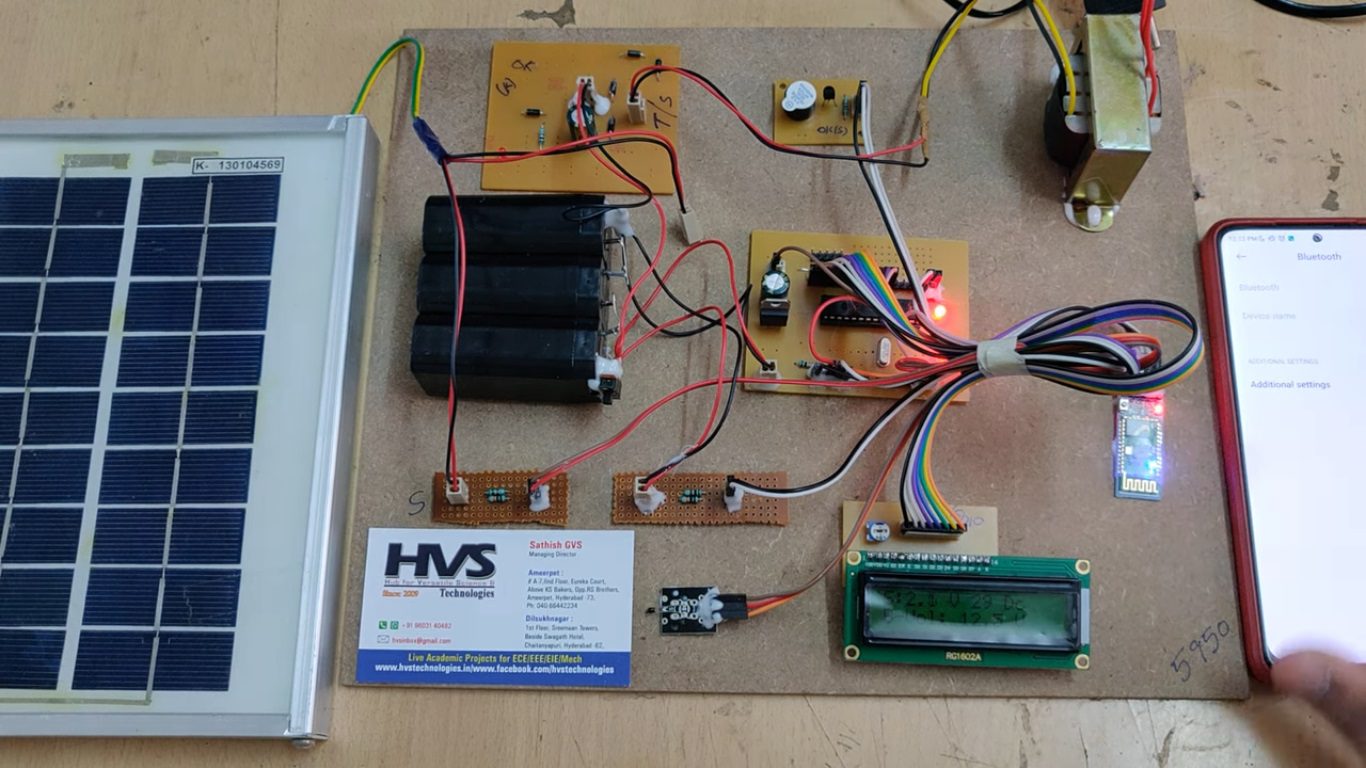
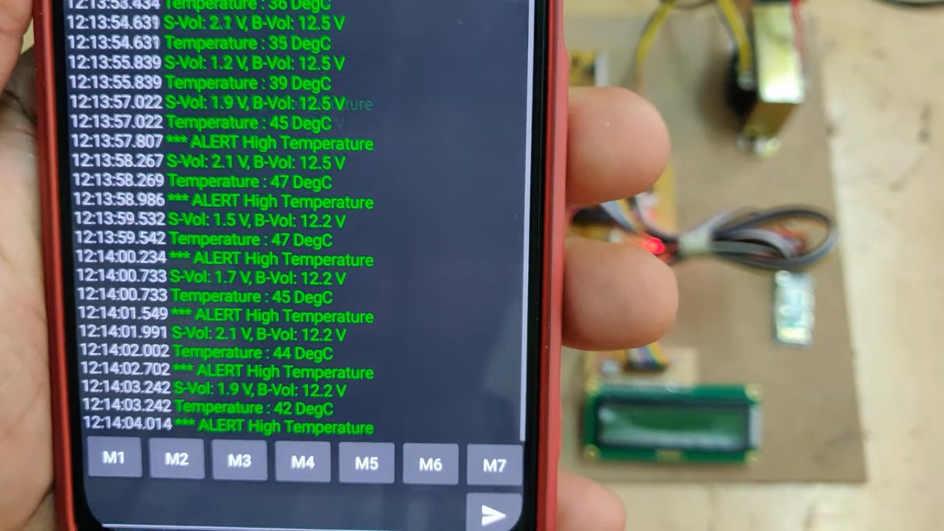
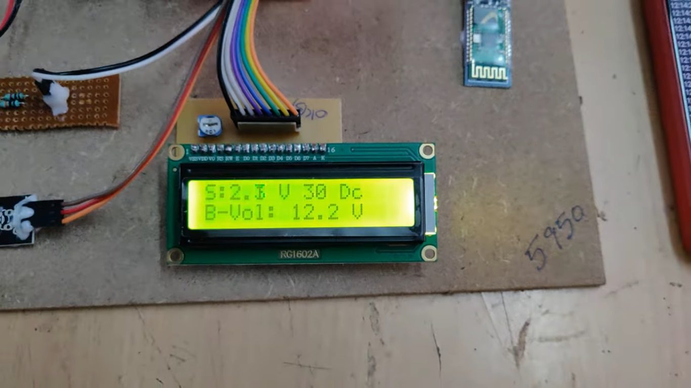
This system also continuously monitors the status of devices connected to it. In this project we are going to monitor the voltage generated by solar panel and temperature of grid. If any abnormal conditions in grid that is automatically sends to user through microcontroller by using Bluetooth module as a communication media. After completion of the command implementation this system sends the confirmation messages back to the calling user.
“Solar power grid status monitoring and alerting with Android smart phone technology” is a modern era automation system where we can control the status of the appliances from any where in the world. Here the devices to be controlled are interfaced with a Bluetooth module, which is capable of receiving instructions in the form of short message service and performs the necessary tasks. The buzzer gives beep alerts.
Objectives:
 video:
- To monitor power grid parameters such as solar panel voltage and grid temperature in real time.
- To provide remote monitoring and control of grid-connected devices using an Android smartphone via Bluetooth communication.
- To detect abnormal grid conditions and generate instant alerts to the user.
- To transmit status information and control commands between the smartphone and microcontroller using a Bluetooth module.
- To improve the reliability and safety of power grid operation through continuous monitoring and automated alerting.
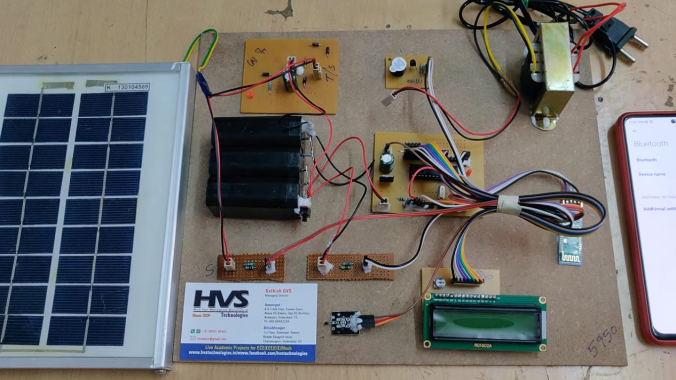
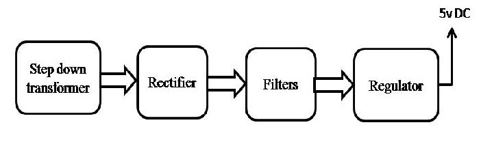
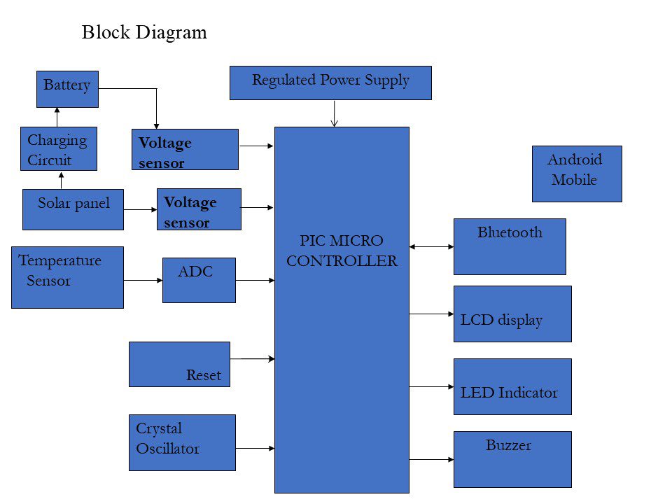
- Regulated power supply.
- PIC Microcontroller.
- Bluetooth module.
- Solar panel
- Charging circuit.
- Rechargeable battery.
- Voltage sensors.
- LCD display.
- Buzzer.
- Crystal Oscillator.
- Reset Button.
- LED Indicators.
- PIC -C for compiling and dumping code into controller
- Express SCH for Circuit design.
Regulated Power Supply:
 video: