No products in the cart.


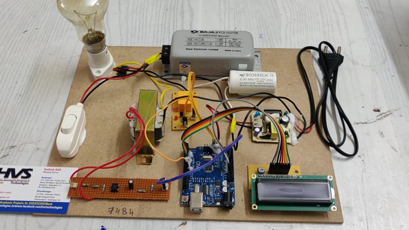
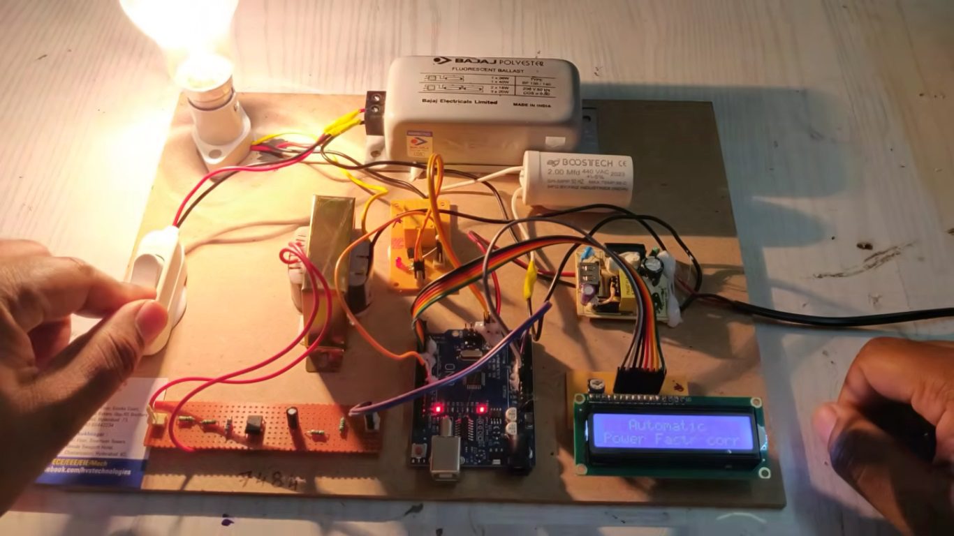
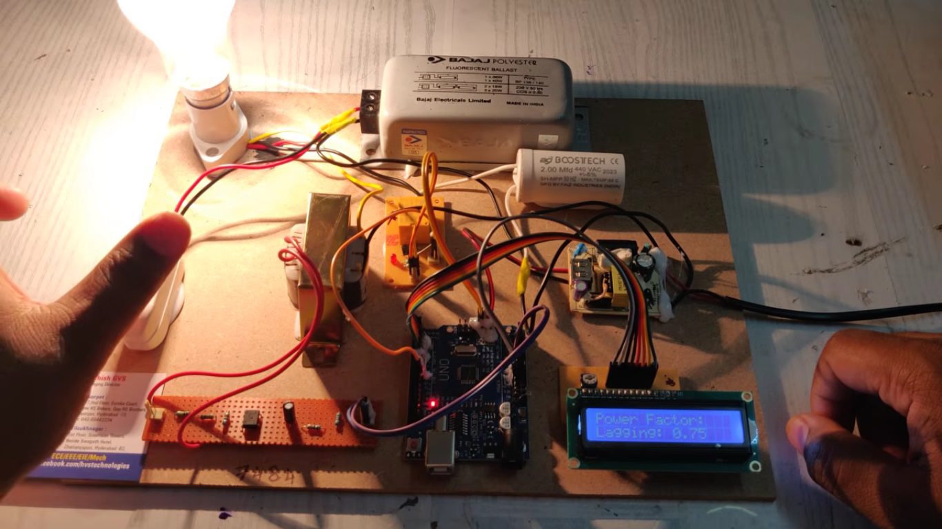
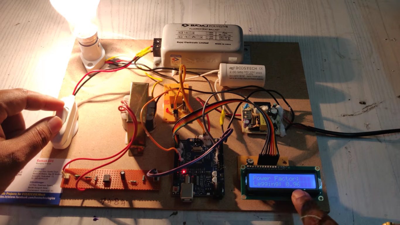
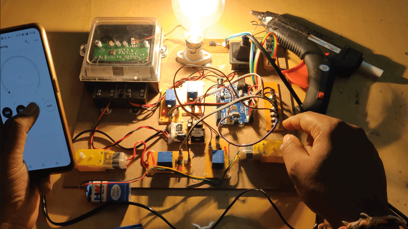
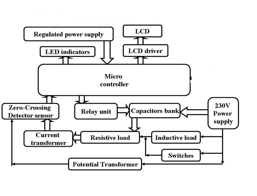
The Automatic Power Factor Correction (APFC) System is designed to improve the power factor of electrical installations by automatically compensating reactive power using capacitor banks controlled by a microcontroller. In industrial and commercial environments, inductive loads such as motors, transformers, and welding machines reduce the power factor, leading to increased power losses, reduced system efficiency, and higher electricity bills. The proposed system continuously monitors the power factor and automatically switches capacitor banks ON or OFF to maintain the power factor close to unity.
The system utilizes an Arduino UNO microcontroller for real-time measurement and control, ensuring efficient power factor correction without manual intervention. Active filtering techniques are also incorporated to reduce.
The developed APFC system enhances energy efficiency, reduces reactive power penalties, minimizes transmission losses, improves voltage regulation, and extends equipment life. Experimental and hardware results demonstrate that the system effectively maintains a power factor above 0.95, providing a reliable and cost-effective solution for modern power management applications.
Objectives
 Block diagram:
video:
Block diagram:
video:
- To measure and monitor the power factor of the electrical system continuously.
- To automatically switch capacitor banks for power factor correction.
- To improve the power factor close to unity (1.0).
- To reduce reactive power losses and electricity charges.
- To enhance overall power quality and system efficiency.
- Arduino UNO Micro controller.
- Regulated Power Supply.
- Resistive load.
- Inductive load.
- Relay bank unit.
- Current transformer.
- Potential transformer.
- Zero-crossing detector.
- LCD display.
- LED indicators.
- Arduino IDE studio compiling and dumping code into Microcontroller.
- Embedded C programming.
- Express SCH for Circuit design.
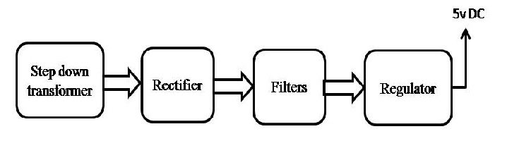 Block diagram:
 video: