Subtotal ₹7,000.00


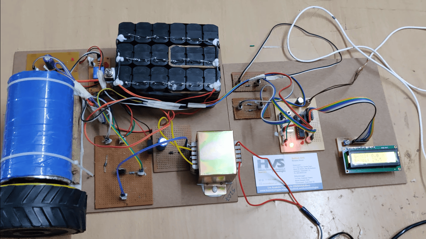
The project is designed to minimize penalty for industrial units using automatic power factor correction unit.
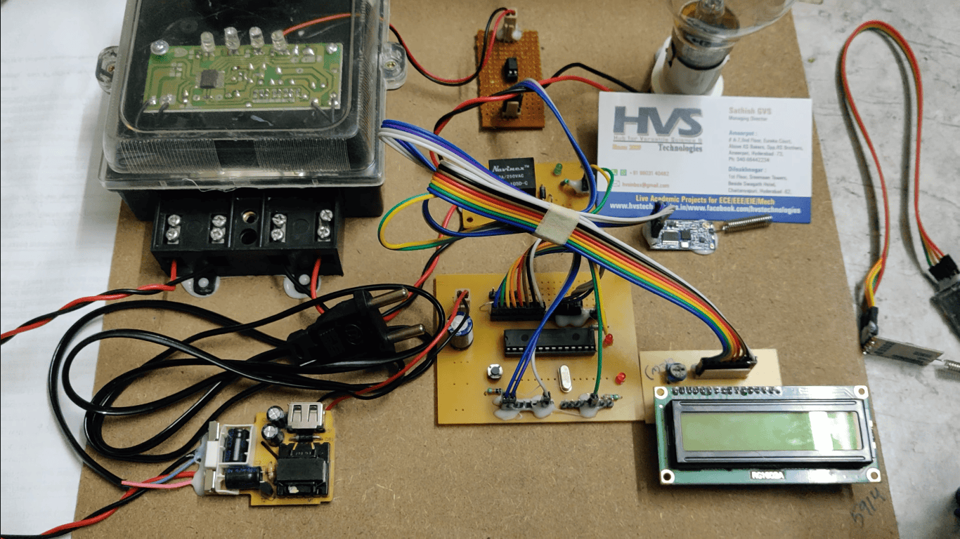
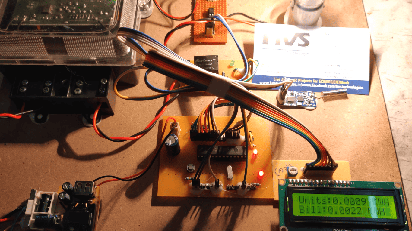
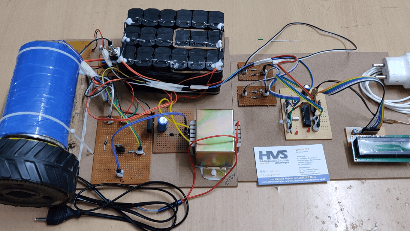
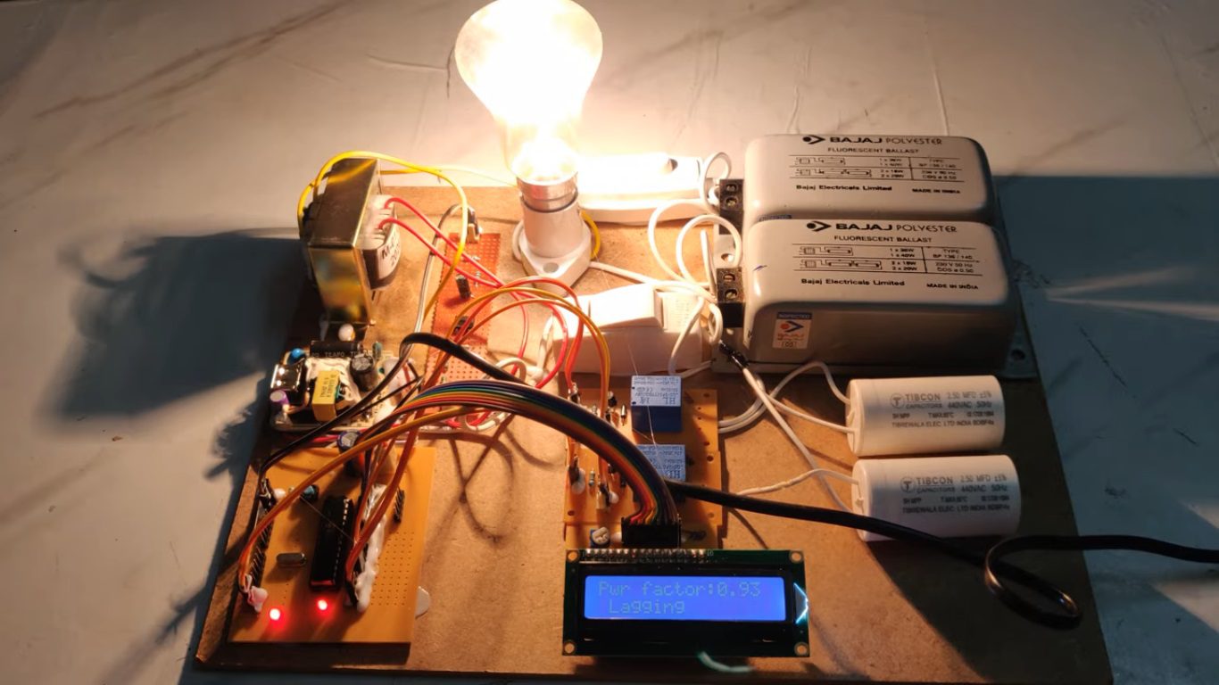
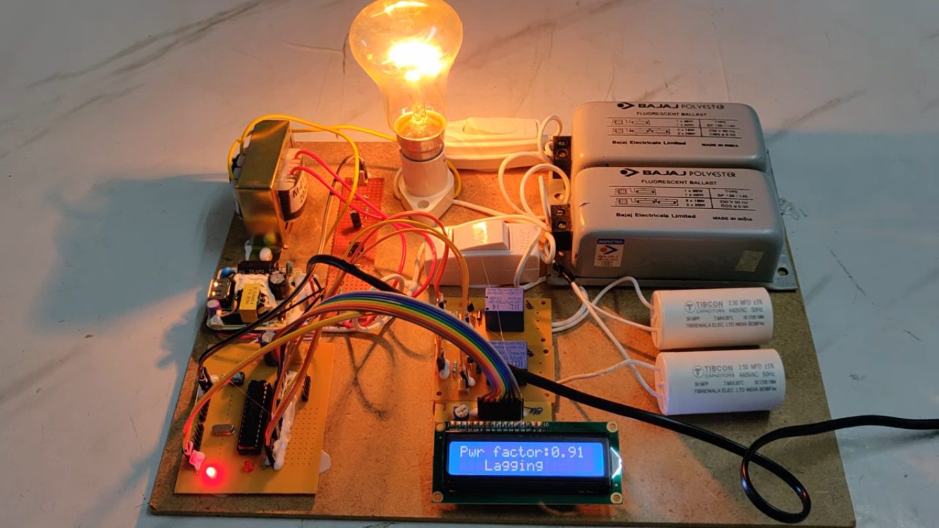
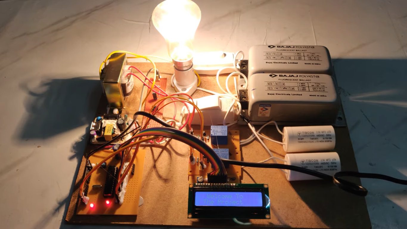
In this proposed system, zero crossing detectors are used for detecting zero crossing of voltage and current. The time lag between the zero-voltage pulse and zero-current pulse is duly generated by suitable operational amplifier circuits in comparator mode is fed to two interrupt pins of a microcontroller. It displays time lag between the current and voltage on an LCD.
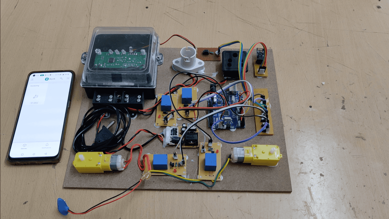
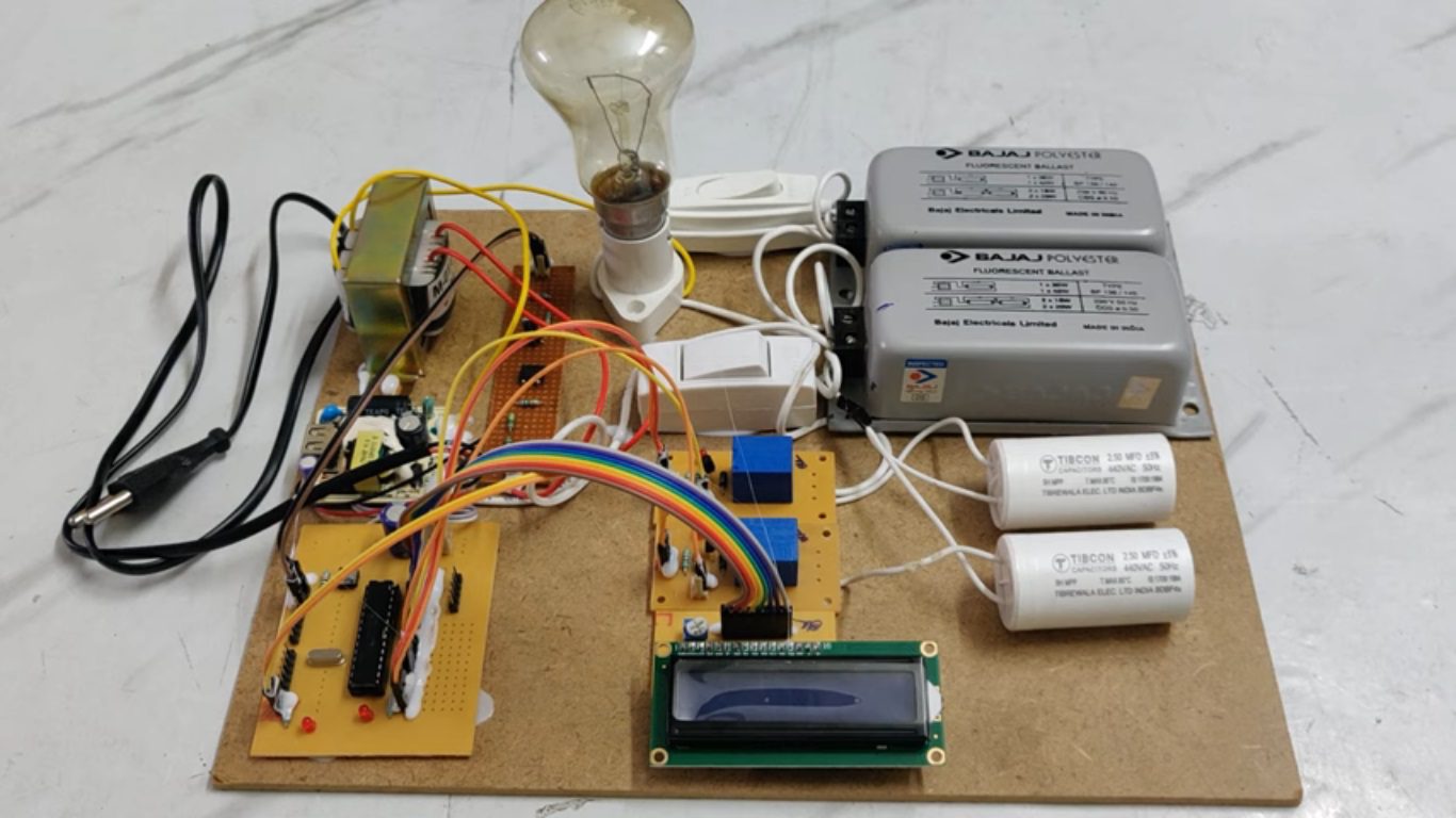
The program takes over to actuate appropriate number of relays from its output to bring shunt capacitors into load circuit to get the power factor till it reaches near unity. The capacitor bank and relays are interfaced to the microcontroller using a relay driver.
Furthermore, the project can be enhanced by using thyristor control switches instead of relay control to avoid contact pitting often encountered by switching of capacitors due to high in rush current.
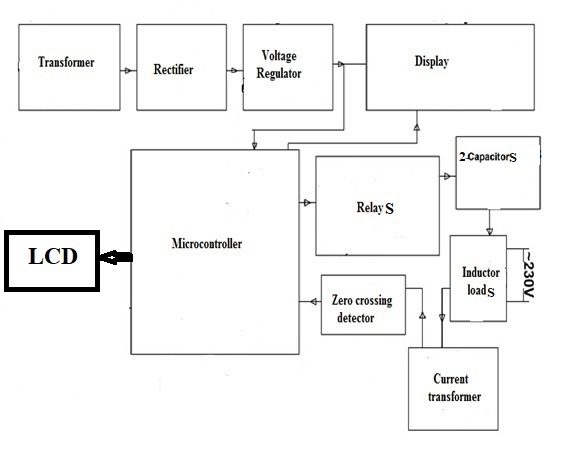
Main blocks used in the project:
 video:
- Regulated power supply.
- PIC Microcontroller.
- Zero crossing detector.
- Voltage regulator.
- Relay.
- Capacitor bank.
- Inductor load.
- Current transformer.
- LCD display.
- PIC C compiler for Embedded C programming.
- Express SCH for Circuit design.
 video: