Subtotal ₹5,250.00


The use of green energy is becoming increasingly more important in today’s world. Therefore, electric vehicles are currently the best choice for the environment in terms of public and personal transportation. Because of its high energy and current density, lithium-ion batteries are widely used in electric vehicles. Unfortunately, lithium-ion batteries can be dangerous if they are not operated within their Safety Operation Area (SOA). Therefore, a battery management system (BMS) must be used in every lithium-ion battery, especially for those used in electric vehicles.
The main aim of the project is to design a battery monitoring and automatic charging system using PIC microcontroller.
A battery stack is limited in performance by the lowest capacity cell in the stack; once the weakest cell is depleted, the entire stack is effectively depleted. The health of each individual battery cell in the stack is determined based on its state of charge (SoC) measurement, which measures the ratio of its remaining charge to its cell capacity. SoC uses battery measurements such as voltage, integrated current and temperature to determine the charge remaining in the battery. Precision single-chip and multichip battery management systems (BMS) combine battery monitoring (including SoC measurements) with passive cell balancing to improve battery stack performance.
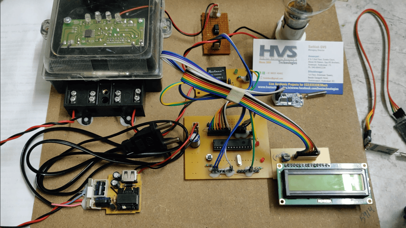
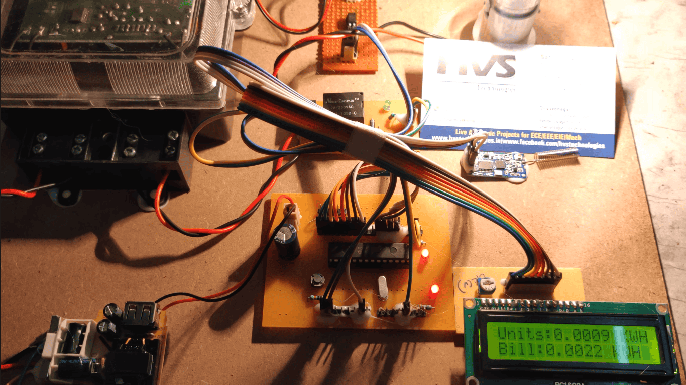
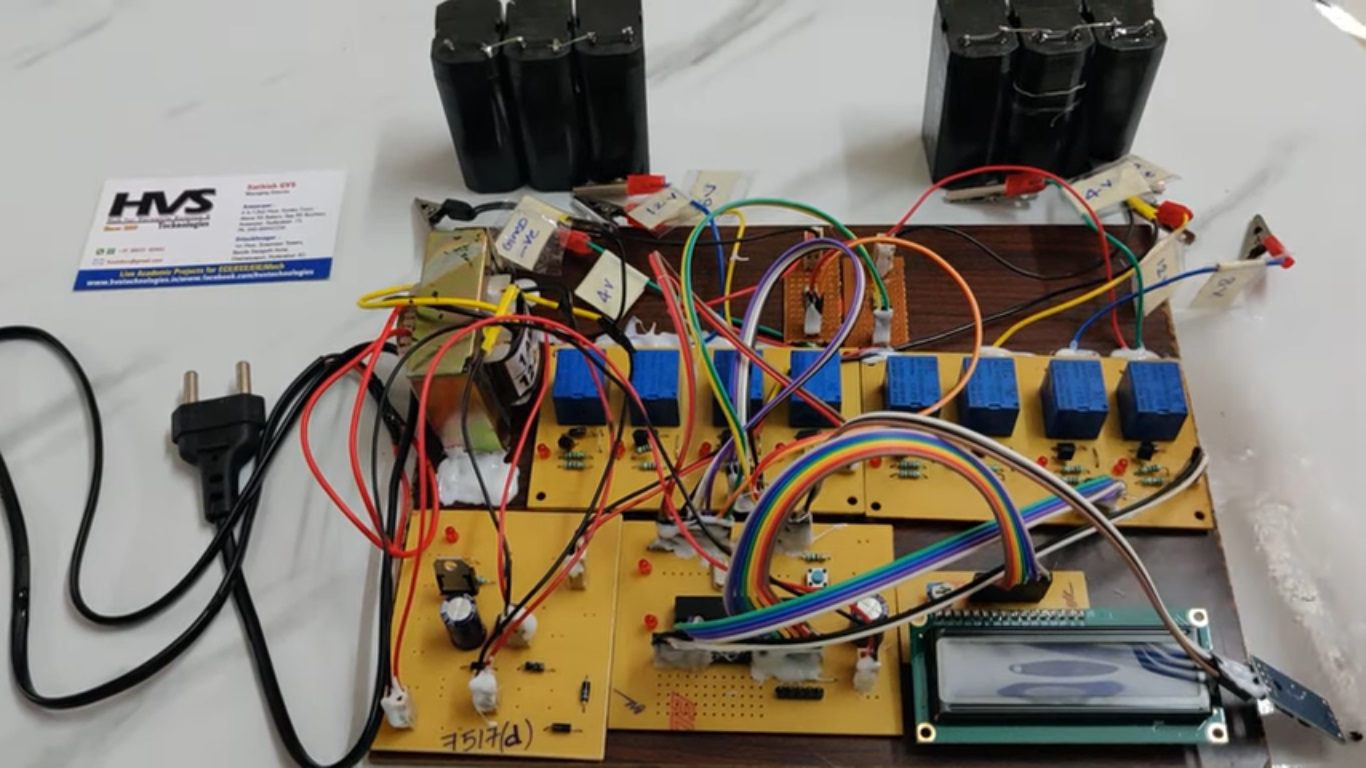
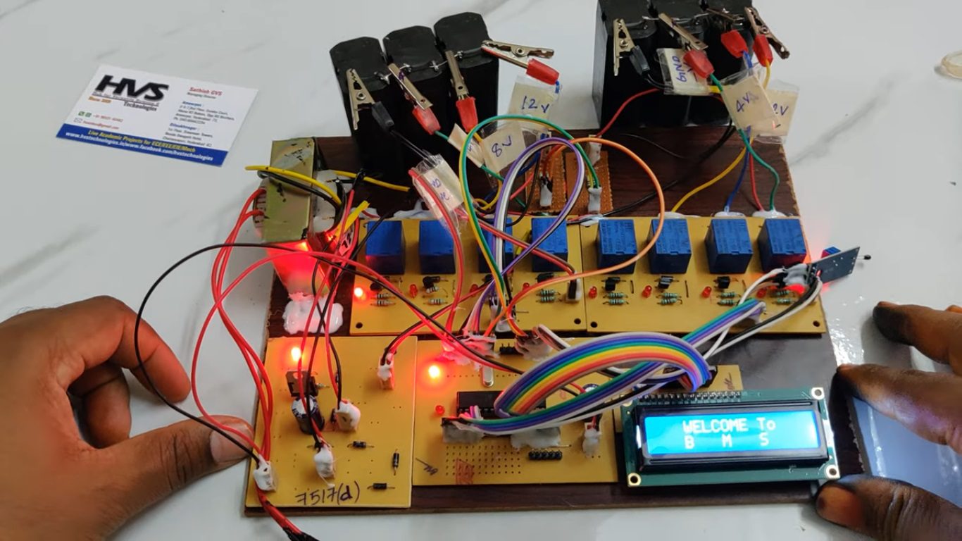
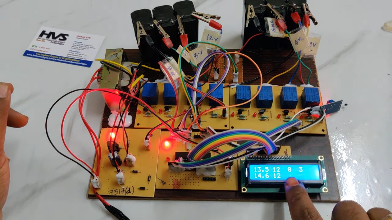
The controlling device of the whole system is PIC microcontroller. The integrated modules to the controller are temperature sensor, Battery packs along with relays, Charger, Buzzer and LCD Module. When any of the battery pack get drained, that battery pack get charged from the charger through relay and the voltage values of each battery pack data is displayed on LCD module as well as it displays the temperature continuously. If the temperature value crosses the set limit, then PIC microcontroller will active the buzzer for alerts. The Microcontroller measures the voltage, current from sensors and based on that it will switch ON/OFF the relays for battery charging. Here relay works as a switch to ON/OFF the charging connection. Microcontroller will monitor the voltage, current and each cell passive balance values on LCD display.
The main objectives of the project:
 video:
- Design a BMS system along with SOC (state of charging) and passive cell and Active cell balance
- High temperature alert using BUZZER.
- Visible alerts using LCD display.
- Regulated power supply
- PIC Microcontroller.
- Temperature sensor.
- Voltage sensor.
- Buzzer.
- Two battery packs.
- Eight Relays.
- Charging Circuit.
- LCD display.
- LED Indicators.
- Crystal oscillator
- Reset button.
- PIC-C compiler for Embedded C programming.
- PIC kit 2 programmer for dumping code into Micro controller.
- Express SCH for Circuit design.
 video: