No products in the cart.


The main objective of this project is to design a pseudo DC-link EV home charger for supply the current uninterruptedly irrespective of any disturbance.
Pseudo-DC link structure avoids the necessity for a DC-link capacitor and associated charging diode between the boosting and inverter stages. The proposed inverter's excellent boosting ability allows it to work with a wide input voltage range.
Moreover, the feature of continuous output current (COC) makes the realization of the possible for an EV home charger. In the pseudo dc-link method, the output current of the dc-dc converter is regulated to be a rectified sinusoidal shape, so that the dc-ac converter connecting to the grid can be implemented as an unfolding bridge switching at the grid frequency. Consequently, the switching loss of the EV charger will be reduced, and its efficiency increased.
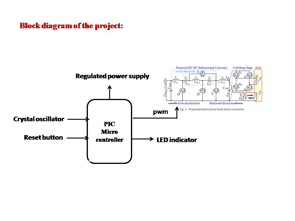
In this project, in order to obtain high voltage step-down and step-up gain with a higher value of UF (utilization factor) a new BBB (bidirectional buck boost) converter with quadratic voltage gain in both directions is proposed. Unlike previous converters, the quadratic voltage gain in both directions is combined with the ability to have a continuous current at both input and output terminals. The continuous input current (CIC) makes it suitable for battery applications such as EV charging in G2V(Grid to Vehicle) and V2G(Vehicle to Grid) applications. The continuous output current, enables the use of the pseudo dc link method and the use of an unfolding bridge for the dc-ac stage which can increase the efficiency of proposed EV charger application. Furthermore, a PIC microcontroller is adapted for battery current control directly by switching the mosfets using PWM method, which offers accurate, fast, and smooth operations under different states of charge (SoC). The electrical common ground between input and output terminals only in the dc-dc stage is preserved and the semiconductor device UF is higher than the main competitors.
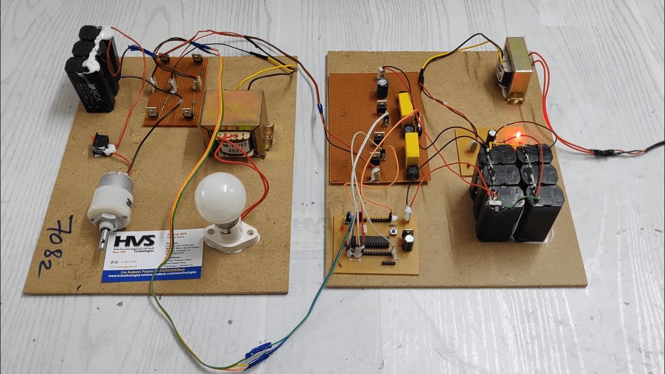
The major building blocks of this project are:
 Block Diagram:
video:
Block Diagram:
video:
- Bidirectional dc-dc converter.
- EV home charger.
- Pseudo dc-link method.
- Utilization factor.
- PIC microcontroller.
- Crystal oscillator.
- Reset button.
- LED indicator.
- PIC-C compiler for Embedded C programming.
- PIC kit 2 programmer for dumping code into Micro controller.
- Express SCH for Circuit design.
 Block Diagram:
 video: